


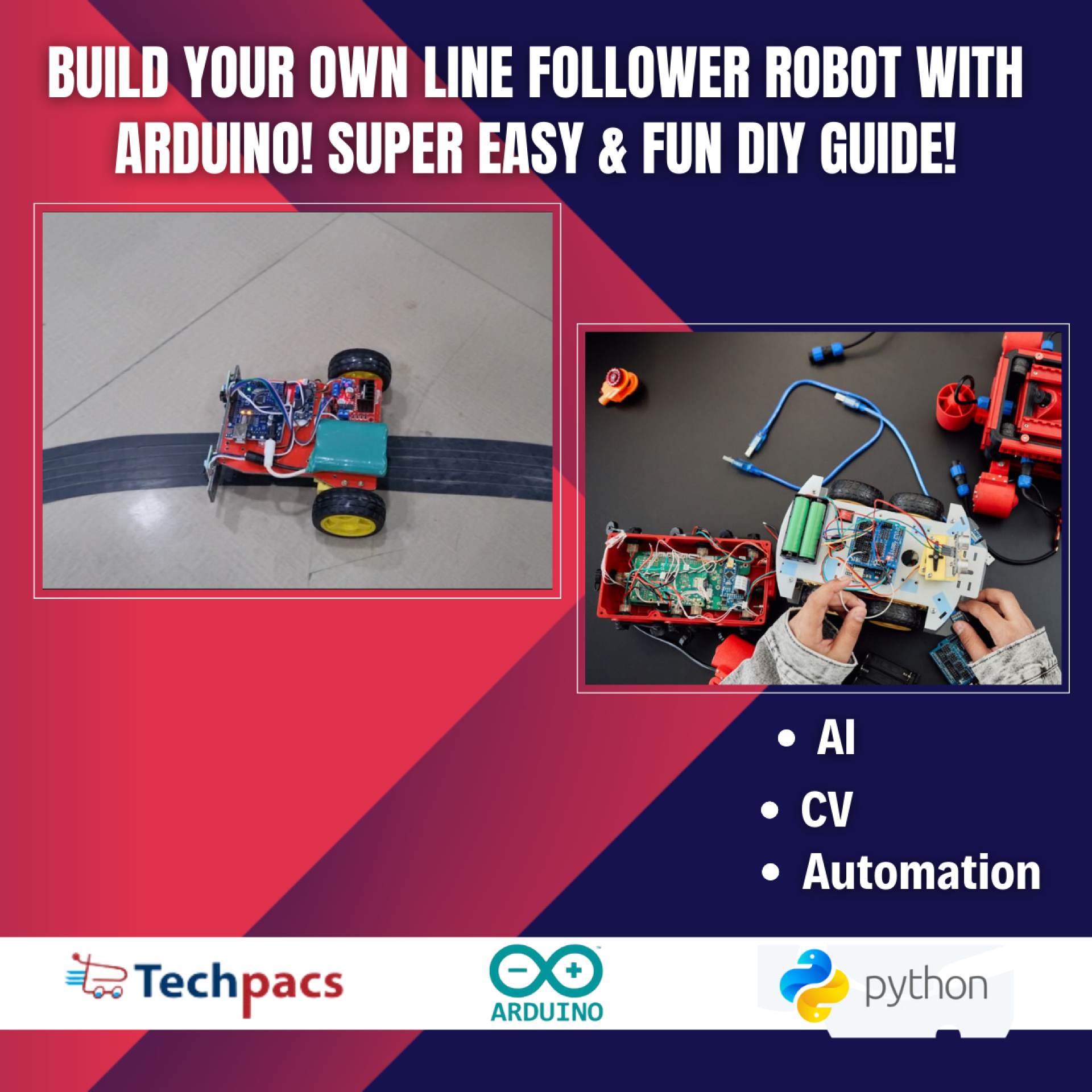
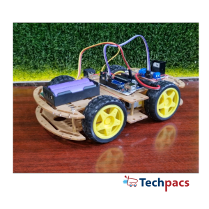
DIY Arduino Line Follower Robot with Step-by-Step Instructions
Building a DIY Arduino Line Follower Robot is an engaging and educational project that introduces you to the fascinating world of robotics and control systems. By leveraging the capabilities of an Arduino microcontroller, you'll learn how to interface with multiple sensors and motors to create a robot that can autonomously follow a path. This project not only enhances your understanding of electronics, programming, and mechanical design but also showcases the practical applications of automation technology. With step-by-step instructions, this project is suitable for both beginners and enthusiasts looking to deepen their knowledge in robotics.
Objectives:
To build a robot that can follow a pre-defined path using line detection sensors.
To understand the interfacing and programming of sensors with Arduino.
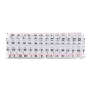
To develop skills in soldering, circuit design, and prototyping.
To implement motor control using an L298N motor driver and Arduino.
To enhance problem-solving skills by debugging and refining the robot's performance.
Key features:
Arduino Uno microcontroller for versatile and easy programming.
Line tracking sensors to detect the path and guide the robot.
L298N motor driver to control the speed and direction of the motors.
Efficient power management using 18650 Li-ion batteries.
Modular and extensible design for potential upgrades and enhancements.
Application Areas:
Line follower robots have a wide range of applications across different fields. In the industrial sector, they are often used for automated material transport in manufacturing plants and warehouses, significantly increasing efficiency and reducing human labor. In educational environments, line follower robots serve as an excellent teaching tool for introducing students to robotics, programming, and electronic systems. Additionally, these robots are also utilized in research and development for prototyping new control algorithms and in competitions to encourage innovation and practical problem-solving among participants. The simplicity and adaptability of line follower robots make them an essential part of both practical applications and learning platforms.
Detailed Working of DIY Arduino Line Follower Robot with Step-by-Step Instructions :
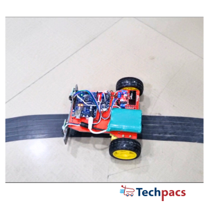
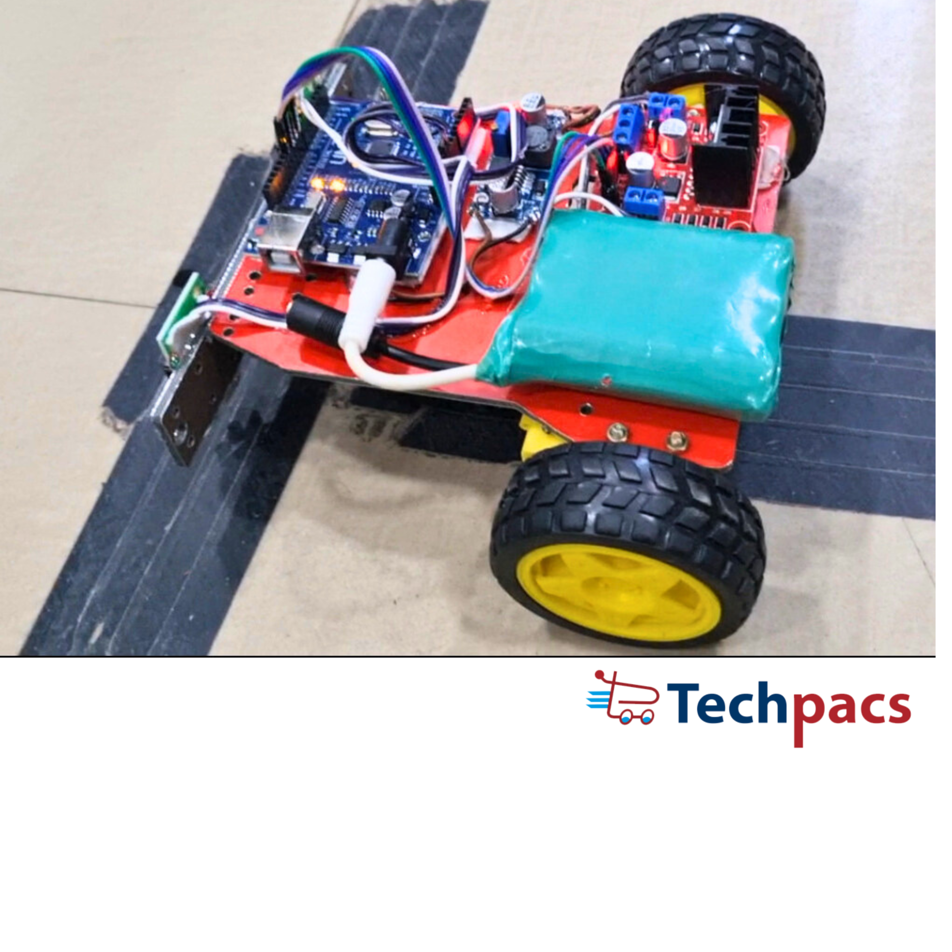
In this project, we build a line-following robot using an Arduino microcontroller, line sensors, a motor driver, and DC motors. The purpose of the robot is to follow a specified path using data from sensors to make real-time decisions. Let's delve into the circuit diagram to understand the intricate workings of this line follower robot.
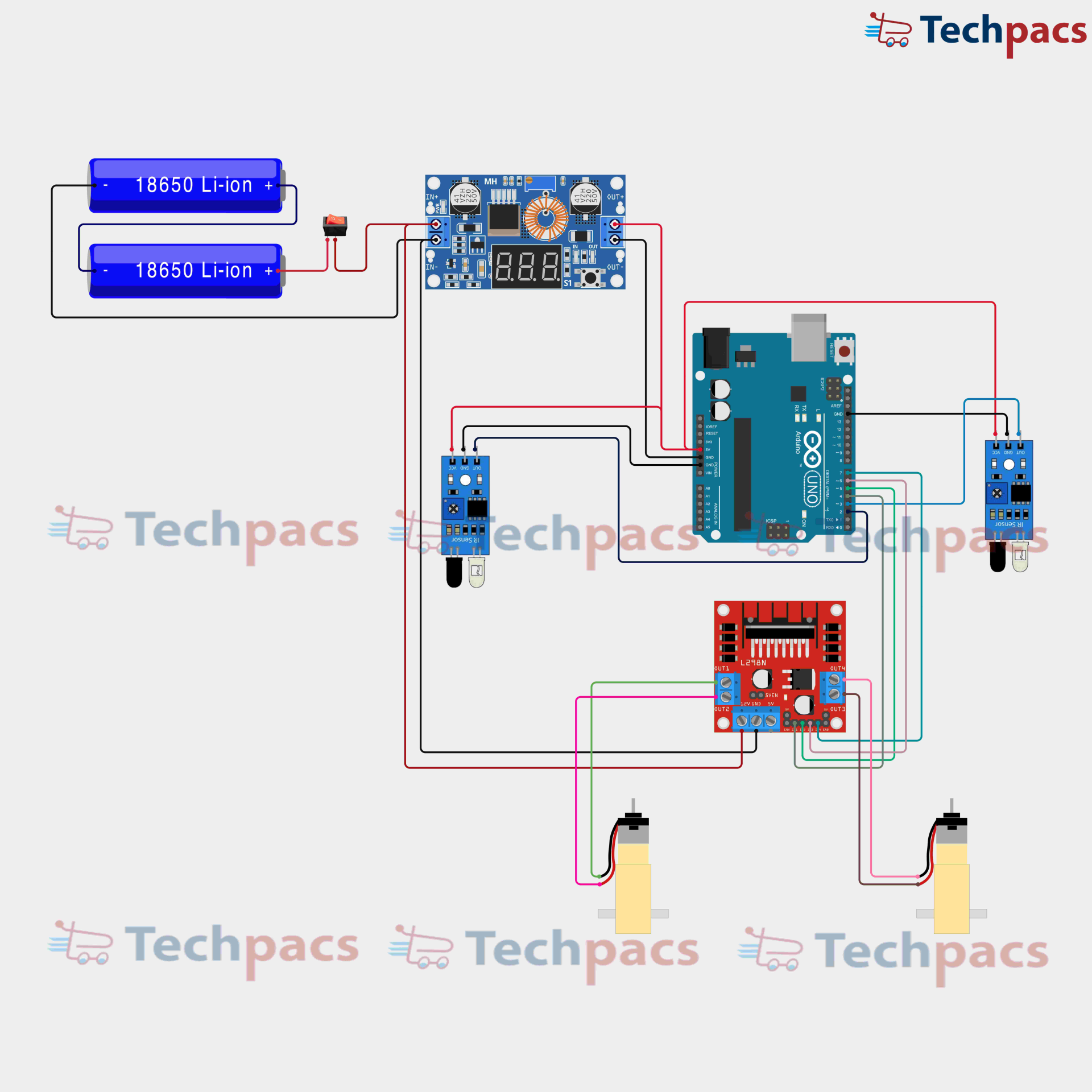
The heart of this project is the Arduino Uno microcontroller, which is responsible for processing the input signals from the sensors and sending corresponding output signals to the motor driver to control the motors. The power supply comprises two 18650 Li-Ion batteries connected in series, ensuring that the system receives adequate voltage and current for operation. This power is routed through a DC-DC step-down module for voltage regulation to match the requirements of the Arduino and the motors.
At the forefront of sensing are two infrared (IR) sensors mounted on the underside of the robot, one on the left and one on the right. These sensors are essential in detecting the line that the robot is meant to follow. The IR sensors emit infrared light and detect its reflection from the surface. When the sensors read a low reflection (indicating a black line), they send a LOW signal to their respective pins on the Arduino. Conversely, a high reflection (off the white surface) sends a HIGH signal to the Arduino.
The Arduino continuously reads these signals to determine the position of the line relative to the robot. This data flow begins with the left and right sensors sending their digital signals to specific input pins on the Arduino. The Arduino processes these signals using a defined algorithm, generally an if-else logic, to make decisions. For instance, if both sensors detect the white surface (sending HIGH signals), the robot moves forward. If the left sensor detects a black line (LOW) while the right sensor detects white (HIGH), this implies that the robot is veering left, prompting the Arduino to correct by steering right. Conversely, if the right sensor detects a black line and the left one does not, the robot should steer left.
The decisions made by the Arduino are transmitted as a series of HIGH or LOW signals to the L298N motor driver module, connected to output pins on the Arduino. The L298N motor driver board is essential for actuating the DC motors, which are connected to it. The motor driver receives control signals from the Arduino to regulate the speed and direction of the motors. This motor driver essentially serves as an intermediary that amplifies the low-power control signals from the Arduino into high-power signals capable of driving the motors, ensuring adequate torque and speed.
Each of the two output channels on the L298N is connected to a DC motor responsible for driving the left and right wheels of the robot. When the Arduino signals the motor driver to move forward, it energizes both motors to rotate in the same direction. To turn left, the motor driver stops or slows down the left motor while maintaining or increasing the speed of the right motor. Conversely, to turn right, it stops or slows down the right motor while maintaining or increasing the speed of the left motor. The motors' speeds are manipulated through pulse-width modulation (PWM) signals sent by the Arduino to the motor driver, allowing for smooth acceleration and deceleration.
Through this seamless flow of data, from sensors detecting the line to the Arduino processing this information to the motor driver executing the movement instructions, the line follower robot adheres to its intended path. This intricate interaction between hardware components and software logic exemplifies the efficiency and elegance of automation projects using Arduino.

Modules used to make DIY Arduino Line Follower Robot with Step-by-Step Instructions :
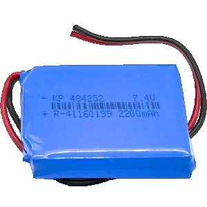
1. Power Supply Module
The power supply module is essential for providing a stable voltage supply to the entire circuit. In this project, we use 18650 Li-ion batteries connected in series to deliver sufficient voltage. The batteries are connected to a voltage regulator module, which steps the voltage down to a level that is appropriate for the Arduino and other connected components. This module ensures that all the electronic parts receive a constant voltage, thus preventing damage due to power surges. The regulated output is then distributed to the Arduino board and the motor driver module, enabling them to function correctly.
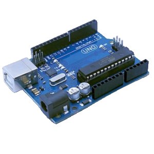
2. Arduino Module
The Arduino Uno serves as the brain of the line follower robot. It receives input signals from the infrared (IR) sensors and processes these signals to control the motors via the motor driver module. The Arduino is programmed to read analog or digital signals from the IR sensors, which detect the presence of a line or track. Depending on the sensor readings, the Arduino generates appropriate control signals that drive the motors in such a way that the robot follows a predetermined path. The control logic is implemented in the Arduino code, making it crucial for the robot's decision-making process.
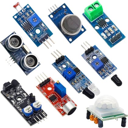
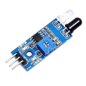
3. IR Sensor Modules
IR sensor modules are used to detect the line or track on the ground, which the robot needs to follow. Each sensor module consists of an emitter and a receiver. The emitter sends out infrared light, which gets reflected back by the white surface of the line. The receiver picks up this reflected light and generates a corresponding electrical signal. When the robot deviates from the line, the signal pattern changes, prompting the Arduino to correct the motors' direction to align with the path again. These sensors are strategically placed on the robot to maximize the detection accuracy and response time.
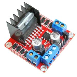
4. Motor Driver Module
The motor driver module receives control signals from the Arduino to drive the DC motors that move the robot. A common choice is the L298N driver, which can control the direction and speed of two motors independently. The motor driver amplifies the low-power control signals from the Arduino into higher-power signals that can drive the motors. Depending on the input from the IR sensors, the motor driver will adjust the motor speeds and directions to follow the path accurately. It bridges the gap between the low-power logical components and high-power mechanical actuators, ensuring efficient operation of the robot.
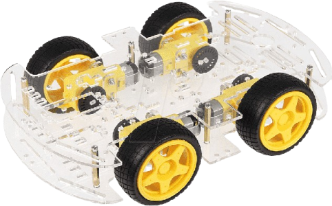
5. DC Motors
The DC motors are the actuators that physically move the robot. They are connected to the motor driver module, which controls their rotational direction and speed. The motors receive their power from the motor driver, which is further controlled by the Arduino based on the input from the IR sensors. Each motor is typically connected to a wheel, enabling the robot to turn and move forward or backward. By varying the speed and direction of each motor, the robot can follow a designated path or line on the ground, executing precise maneuvers as dictated by the programmed logic in the Arduino.
Components Used in DIY Arduino Line Follower Robot with Step-by-Step Instructions :
Power Supply Module
18650 Li-ion Batteries
These batteries provide the main power source for the entire circuitry and motors in the robot.
DC-DC Buck Converter
This module steps down the voltage from the batteries to a level suitable for the Arduino and other components.
Switch
The switch is used to turn the power supply on and off for the robot.
Control Module
Arduino Uno
This is the main microcontroller that processes sensor data and controls the motors to follow the line.
Sensing Module
IR Sensors
These sensors detect the presence of a line by reflecting IR light off the surface and sending the data to the Arduino.
Motor Driver Module
L298N Motor Driver
This component takes signals from the Arduino and controls the direction and speed of the motors accordingly.
DC Geared Motors
The motors drive the wheels of the robot, enabling movement based on the commands received from the motor driver.
Other Possible Projects Using this Project Kit:
Obstacle Avoidance Robot
Using the same project kit meant for the line follower robot, you can create an Obstacle Avoidance Robot. This robot would use ultrasonic sensors instead of infrared sensors to detect obstacles in its path and navigate around them. The Arduino would process data from the ultrasonic sensors to calculate distances to obstacles. By modifying the logic in the Arduino code to control motor direction based on the distance to objects, you can ensure that the robot avoids collisions. Adding a servo motor to rotate the ultrasonic sensor can improve obstacle detection, giving the robot a broader scanning range.
Light Following Robot
Another interesting project is a Light Following Robot. This robot would move towards the light source using light-dependent resistors (LDRs). By replacing the infrared sensors with LDRs, the Arduino can read the analog values corresponding to the light intensity. By comparing the values from multiple LDRs placed on different sides of the robot, the Arduino can determine the direction from which the light is coming and steer the motors to move toward it. Adjusting the sensitivity and threshold values in the Arduino code will allow for fine-tuning the robot's behavior to follow the light effectively.
Edge Detection Robot
The project kit can also be used to make an Edge Detection Robot. This type of robot can navigate a table or platform without falling off the edge. By utilizing infrared sensors positioned at the edge of the robot, the Arduino can detect the absence of reflected signals when the robot approaches the edge of the surface. Programming the Arduino to stop or reverse the motors when an edge is detected ensures the robot stays on the platform. This project is particularly useful for creating robots with the ability to navigate elevated surfaces safely.
Bluetooth Controlled Robot
You can also build a Bluetooth Controlled Robot using this project kit by integrating a Bluetooth module with the Arduino. The user can send commands to the robot via a smartphone app. The Arduino will decode these commands and control the motors accordingly. This project requires modifying the Arduino code to handle Bluetooth communication and control the motor driver based on received commands. This project showcases wireless control capabilities, allowing for remote operation of the robot with enhanced control and flexibility.
| Shipping Cost |
|
No reviews found!


No comments found for this product. Be the first to comment!