


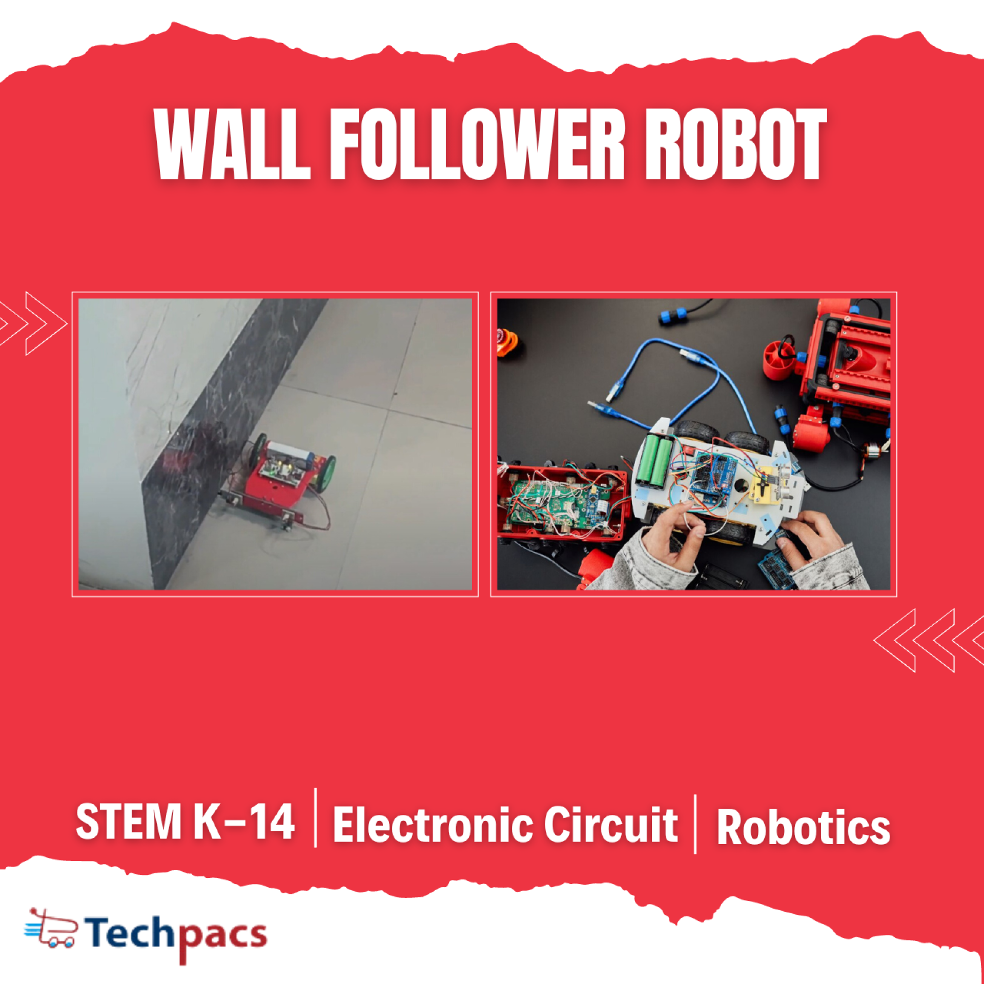
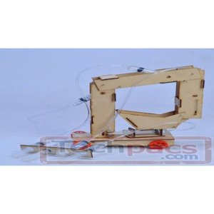
Wall Follower Robot for Learning Robotics and Navigation
The Wall Follower Robot is a practical project designed to introduce students and enthusiasts to the basics of robotics and navigation. Utilizing sensors and motors, this robot is programmed to follow the contours of a wall, demonstrating fundamental principles of obstacle detection and autonomous path following. Through constructing this project, learners gain hands-on experience with electronic components, circuit design, and programming, fostering a deeper understanding of how robots perceive and interact with their environment. This project is ideal for those looking to expand their knowledge of robotics, electronics, and practical application of sensor-based navigation systems.
Objectives
1. To design and build a robot capable of following a wall using infrared sensors.
2. To implement basic navigation algorithms enabling autonomous movement along the wall.
3. To provide hands-on experience in electronics, circuit design, and microcontroller programming.
4. To enable understanding of sensor integration and data processing for robotic control.
5. To demonstrate practical application of robotics in real-world navigation tasks.
Key Features
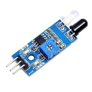
1. Infrared sensors for detecting distance from the wall.
2. Autonomous navigation using microcontroller-based control logic.
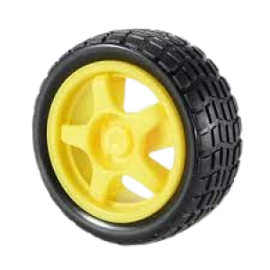
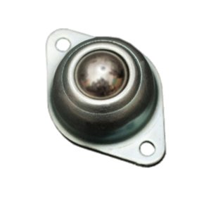
3. Dual motor drive system for precise movement and control.
4. LED indicators for power and operational status display.
5. Rechargeable battery system for extended use and sustainability.
Application Areas
The Wall Follower Robot has numerous application areas in both educational and practical domains. In educational settings, it serves as an excellent tool for teaching robotics, programming, and electronics, providing students with hands-on experience in building and coding autonomous systems. Practically, such robots can be used in household applications such as automated cleaning devices, where they navigate along walls to clean edges and corners effectively. Additionally, they can be employed in industrial settings for tasks requiring movement along predefined paths, such as inspection robots that follow walls or fences to monitor integrity and security. The fundamental principles learned from building wall followers can also be extended to more complex robotic navigation systems used in autonomous vehicles and drones.
Detailed Working of Wall Follower Robot for Learning Robotics and Navigation
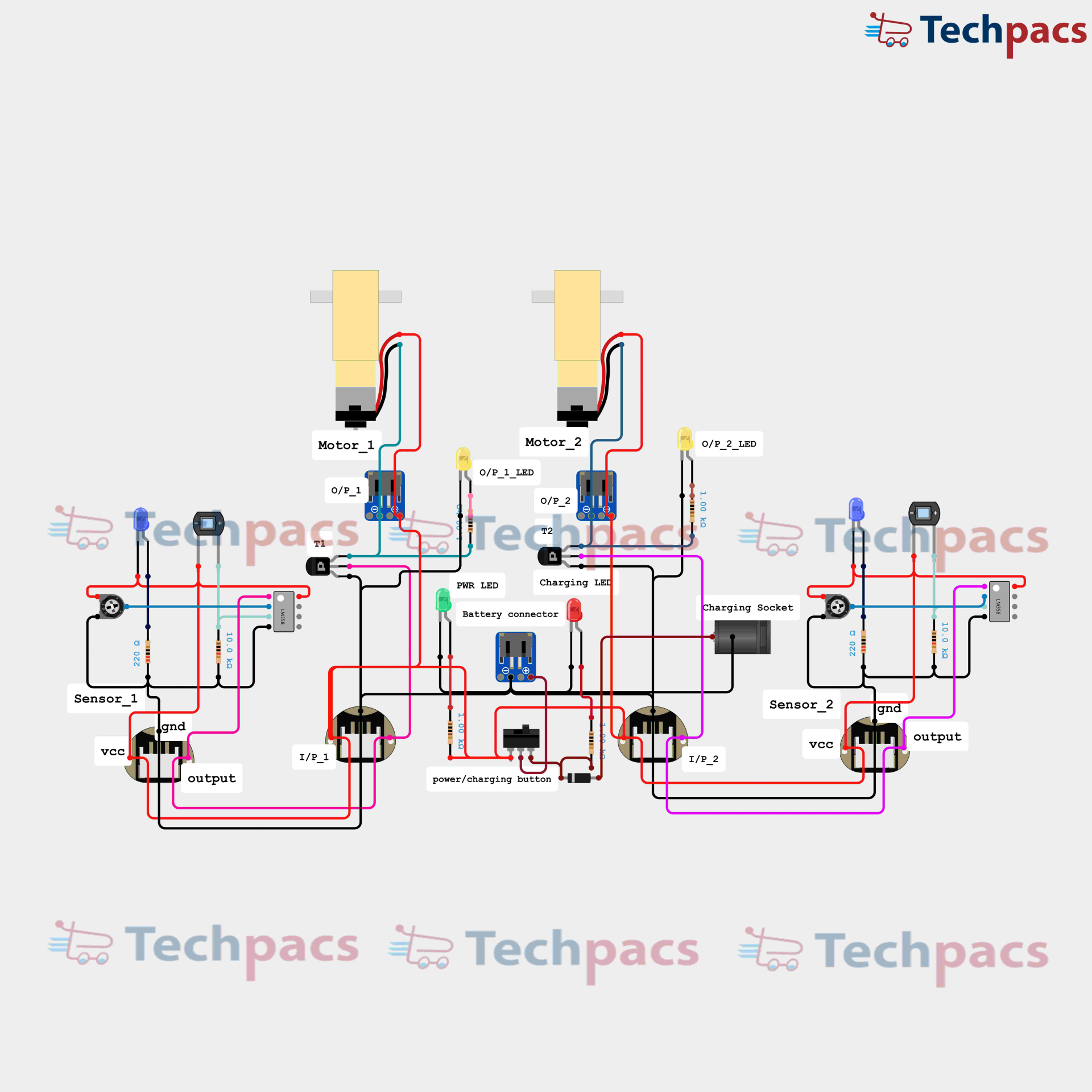
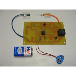
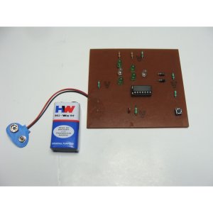
The Wall Follower Robot circuit diagram is a fascinating study of how simple electronic components can be interconnected to perform a complex task, such as navigating alongside a wall. At its core, the circuit involves sensors, motors, and transistors working in unison to achieve the desired behavior. To understand the working of this robot, let's delve into each segment of the circuit and follow the flow of data.
The circuit diagram shows two primary sensors, Sensor_1 and Sensor_2, which detect the presence of a wall and give feedback to the robot. Each sensor has three connections: VCC (power supply), GND (ground), and output. The VCC and GND of each sensor are connected to a power source, ensuring they are operational. The output from these sensors is the critical data that determines how the robot reacts in real time.
Sensor_1 is responsible for monitoring the left side of the robot, while Sensor_2 monitors the right side. When Sensor_1 detects a wall, it sends a high output signal. This high output signal is directed to I/P_1, a critical input node in the circuit. Similarly, if Sensor_2 detects a wall, it outputs a high signal to I/P_2. These inputs (I/P_1 and I/P_2) are connected to transistors T1 and T2, respectively, which act as switches to control the motors, Motor_1 and Motor_2.
Transistors T1 and T2 are essentially the gatekeepers of the motors. When the sensor output is high, the corresponding transistor switches on, allowing current to flow and consequently powering the connected motor. For instance, if Sensor_1 sees a wall and outputs a high signal to I/P_1, transistor T1 turns on, activating Motor_1. If Sensor_2 does the same for the right side, it influences T2 and Motor_2. This mechanism allows the robot to adjust its path dynamically, ensuring it follows the wall closely.
To indicate the activation status of the sensors and motors, the circuit includes various LEDs. Each sensor has its own indicator LED (blue for both Sensor_1 and Sensor_2), which lights up when the sensor detects a wall and sends a high signal. Additionally, motor LEDs (O/P_1_LED and O/P_2_LED) are connected in parallel to Motor_1 and Motor_2 respectively. These LEDs turn on when their corresponding motors are active, providing visual feedback on the robot's operational status.
Power management is another critical aspect of this circuit. The power/charging button, along with the battery connector and charging socket, ensures the robot remains operational and can be conveniently charged when needed. The PWR LED and Charging LED provide indicators for the power status and charging process. When the power button is pressed, the circuit is activated, and power flows to the sensors, transistors, and motors, ensuring every component is ready to perform its role.
Furthermore, the arrangement of the connections is methodical, ensuring no interference between the different components. The motors are placed centrally, receiving inputs from the sides of the robot where the sensors are located. This central placement allows the robot to pivot and adjust its movements efficiently, responding promptly to the signals from the opposing sides. The interconnected wiring showcases a perfect blend of analog and digital signals flowing in harmony to create a responsive navigational system.
In conclusion, the wall follower robot circuit diagram elucidates a systematic approach to robotics and navigation. Through the coordinated efforts of sensors detecting environmental changes, transistors acting as switches, motors making mechanical movements, and LEDs providing visual feedback, the robot manages to perform its wall-following function adeptly. This intricate yet straightforward circuit serves as a valuable learning tool for anyone interested in robotics, showcasing the essential principles of sensor integration, signal processing, and motor control.

Modules used to make Wall Follower Robot for Learning Robotics and Navigation :
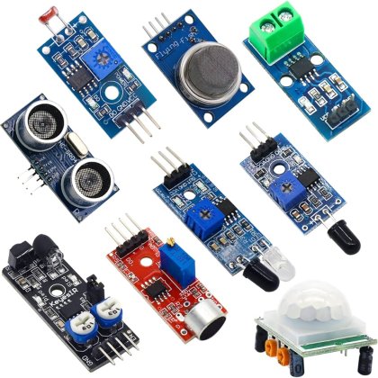
Sensor Module
The sensor module serves as the eyes of the wall follower robot. It includes two distance sensors, Sensor_1 and Sensor_2, placed on either side of the robot to detect the presence and proximity of walls. The sensors typically use infrared or ultrasonic technology to measure distances. Each sensor is connected to the circuit via three pins: VCC (power), GND (ground), and output. The output signal from each sensor is sent to the input pins I/P1 and I/P2. When the sensors detect a wall, they send a corresponding signal, which is then utilized to determine the robot's movement and ensure it maintains a consistent distance from the wall.
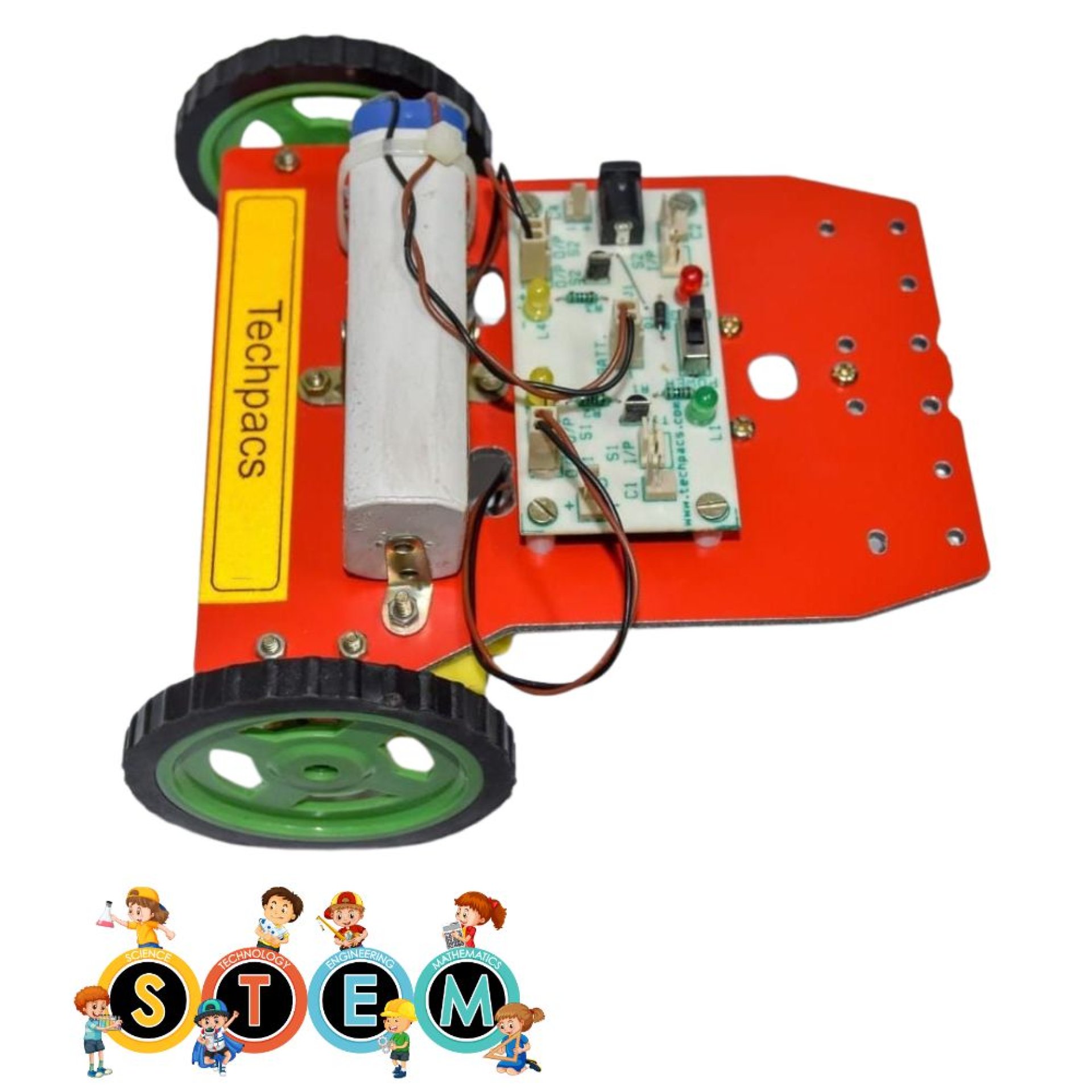
Motor Control Module
This module consists of two DC motors, labeled Motor_1 and Motor_2, each controlling one wheel of the robot. The motors receive signals from transistors T1 and T2, which act as electronic switches. The transistors, in turn, are controlled by the signals received from the sensors through the microcontroller. Based on these signals, the transistors either allow or block current to the motors, thus controlling their speed and direction. Additionally, LEDs labeled as O/P1_LED and O/P2_LED provide visual feedback for the status of each motor. This module ensures the robot navigates efficiently and adjusts its position in response to sensor inputs.
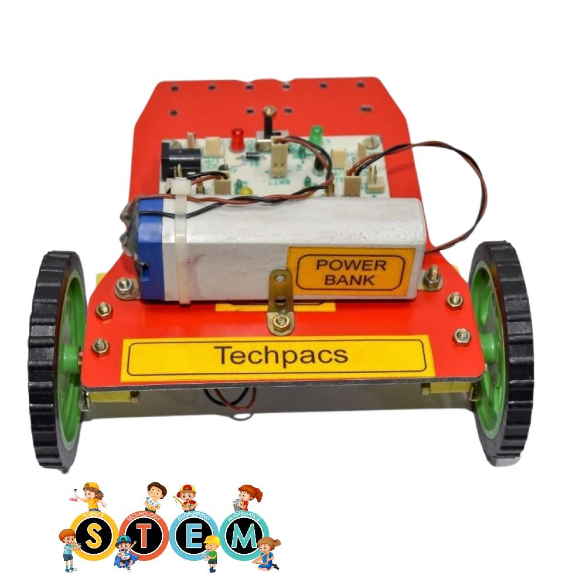
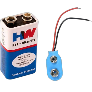
Power Supply Module
The power supply module provides a stable voltage to all components of the robot. It includes a battery, battery connector, and a charging socket for recharging the battery. The battery connector is linked to the primary power lines and is controlled by a power/charging button, which allows switching the robot on and off. The power is then distributed to sensors, motors, and other electronic components ensuring they operate correctly. An additional power indicator LED, labeled as PWR LED, provides a visual indication that the system is powered on. The charging LED shows the status during the charging process.
Microcontroller Module
At the heart of the robot is the microcontroller module, which processes input from the sensors and controls the motors. The microcontroller runs the algorithms that determine the robot's behavior in response to the sensor data. When the sensors detect walls, they send signals to the microcontroller, which processes these signals and calculates the appropriate response, be it turning left, right, or moving forward. This response is then sent to the motor control module to adjust the speed and direction of the motors accordingly. This module is crucial for the decision-making process of the robot.
Indicator LED Module
The indicator LED module comprises several LEDs that provide visual feedback on the robot's status. There are LEDs for power indication (PWR LED), charging indication (CHRG LED), and motor output status (O/P1_LED and O/P2_LED). These LEDs help in diagnosing the status of various subsystems and ensure that they are functioning correctly. For instance, if a motor isn't running, the corresponding LED can help identify if the issue is with the control signal or the motor itself. This module acts as an interface for users to monitor the operation of the robot.
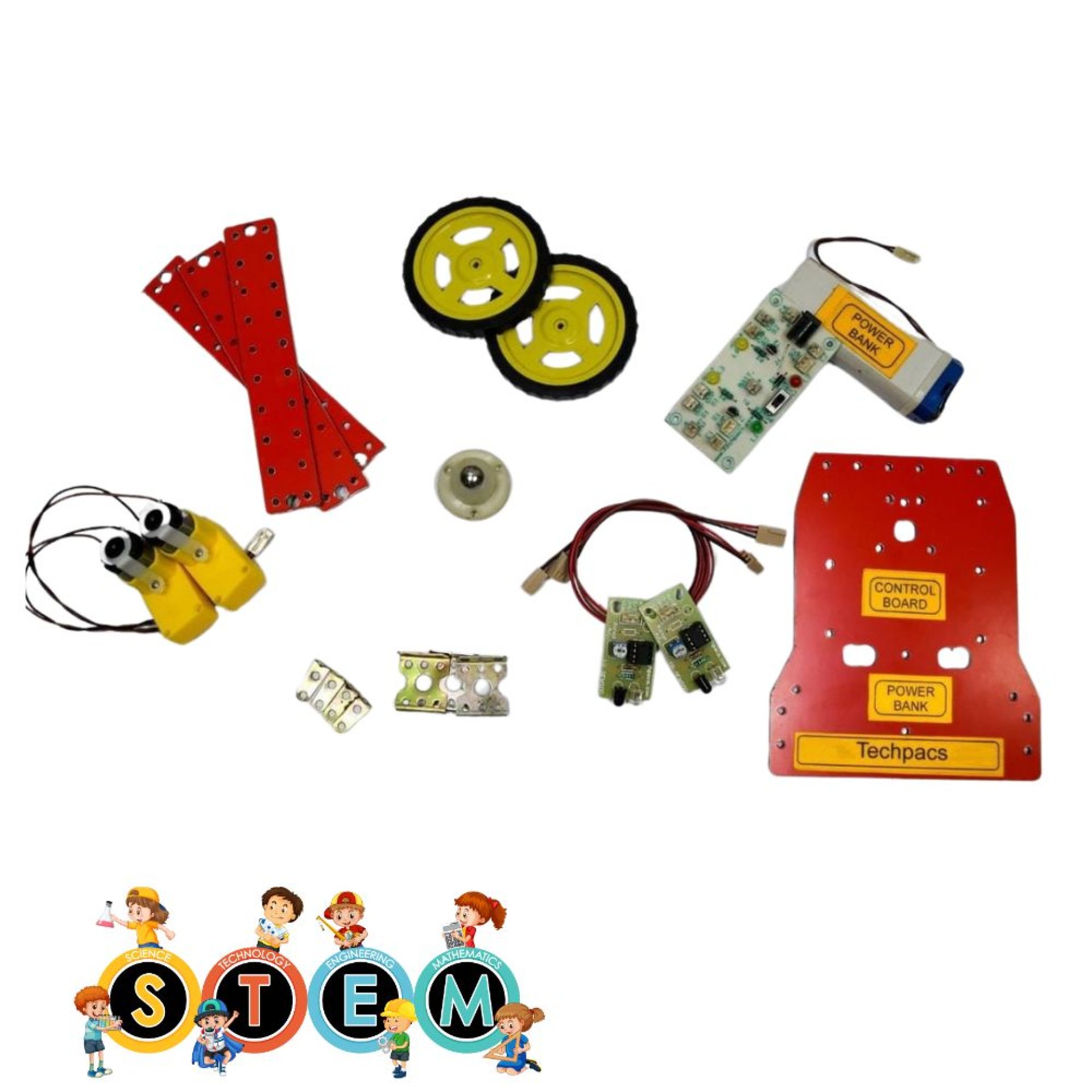
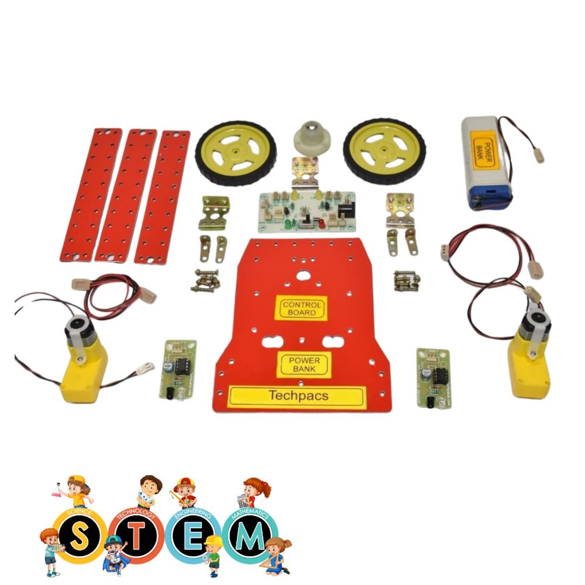
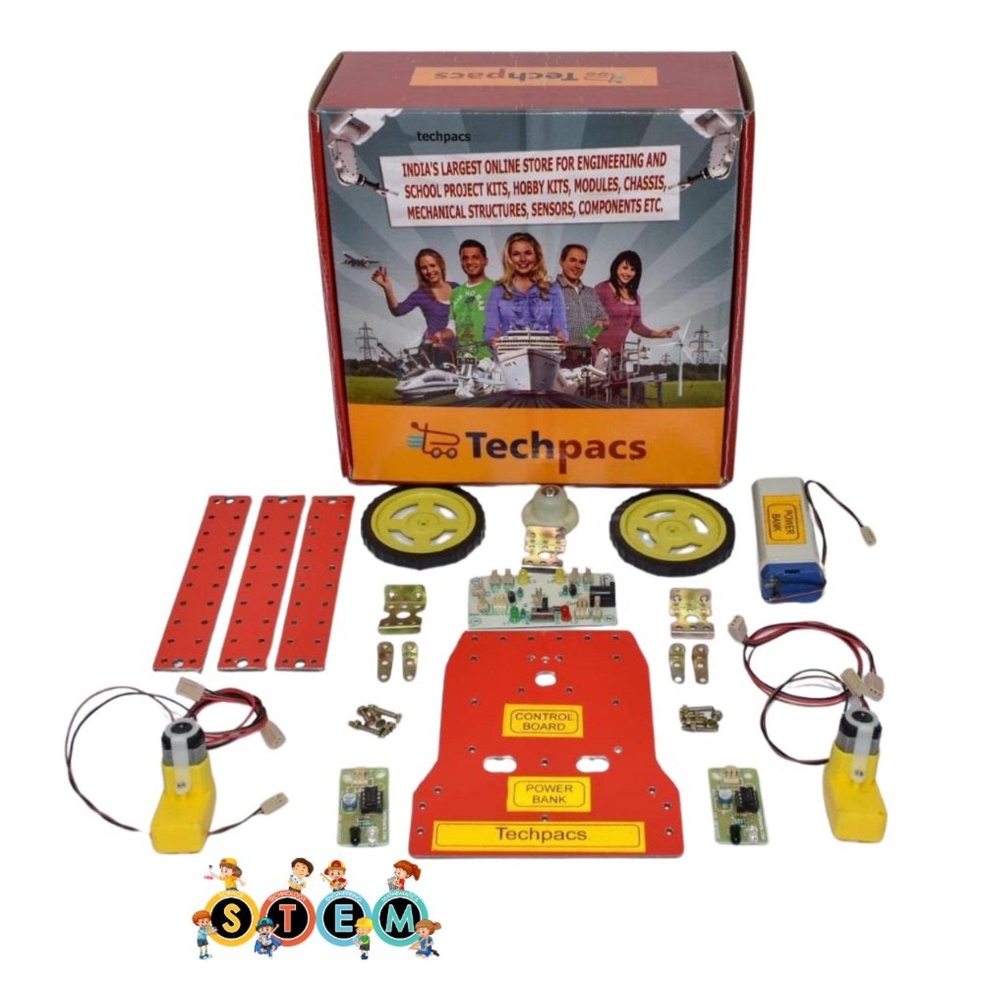
Components Used in Wall Follower Robot for Learning Robotics and Navigation:
Power Supply Module
Battery Connector:
Connects the battery to the circuit, enabling power supply to the entire system.
Charging Socket:
Allows the battery to be charged without disconnecting it from the circuit.
Power/Charging Button:
Switches between powering the circuit and charging the battery.
Motor Control Module
Motor_1 and Motor_2:
Provide propulsion to the robot, allowing it to move along walls.
Transistors T1 and T2:
Act as switches to control the motors, determining the robot's movement.
O/P_1_LED and O/P_2_LED:
Indicate the operational status of the motors, showing if the motors are active or not.
Sensing and Navigation Module
Sensor_1 and Sensor_2:
Detect the distance to the wall and provide inputs to navigate the robot.
Capacitors (ceramic):
Filter out noise in the sensor signals, enhancing stable readings for precise navigation.
Indicators and LED Module
Power LED:
Shows whether the circuit is powered on.
Charging LED:
Indicates the charging status of the battery.
Other Possible Projects Using this Project Kit:
Line Follower Robot
The line follower robot project can be developed using the same project kit components. This robot is designed to detect and follow a line drawn on the floor. The robot uses IR sensors similar to those in the wall follower robot to detect the line's path. When the sensor detects the line, it sends a signal to the microcontroller, which then controls the motors to steer the robot along the line. This project helps in understanding basic concepts of robotics, sensor integration, motor control, and autonomous navigation.
Obstacle Avoidance Robot
Using the same components from the wall follower project kit, an obstacle avoidance robot can be constructed. This robot uses IR sensors to detect any obstacles in its path. When an obstacle is detected, the microcontroller processes the information and navigates the robot to avoid the obstacle by changing its direction. This project introduces concepts such as real-time environment sensing, decision making, and obstacle navigation, providing a solid foundation in interactive robotics and automation systems.
Light Following Robot
A light following robot can be another interesting project, using components such as light sensors along with the existing motors and microcontroller in the project kit. This robot is programmed to move towards the source of light. The light sensors detect the intensity of light and steer the robot accordingly. This project is useful for understanding the principles of sensor integration, signal processing, and robotic movement influenced by external environmental factors.
Maze Solver Robot
The maze solver robot can be another advanced project using the same kit. It involves programming the microcontroller to solve a maze algorithmically using IR sensors for path detection. As the robot navigates through the maze, it uses data from the sensors to make decisions at each junction, determining the best path forward. This project immerses learners in algorithm development, pathfinding techniques, and deeper logic implementation in robotics, making it highly educational and rewarding.
Edge Detection Robot
An edge detection robot is another creative application using the project kit's components. This robot is designed to detect edges or cliffs to avoid falling off surfaces. The IR sensors are positioned in such a way that they detect the presence or absence of a surface beneath them. Upon detecting an edge, the robot reverses or turns to prevent falling. This project highlights how robots can be programmed for accident prevention and safe operations, emphasizing environmental awareness and sensor-based control.
| Shipping Cost |
|
No reviews found!


No comments found for this product. Be the first to comment!