


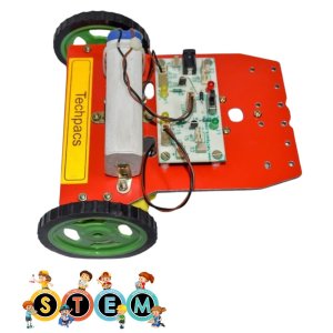


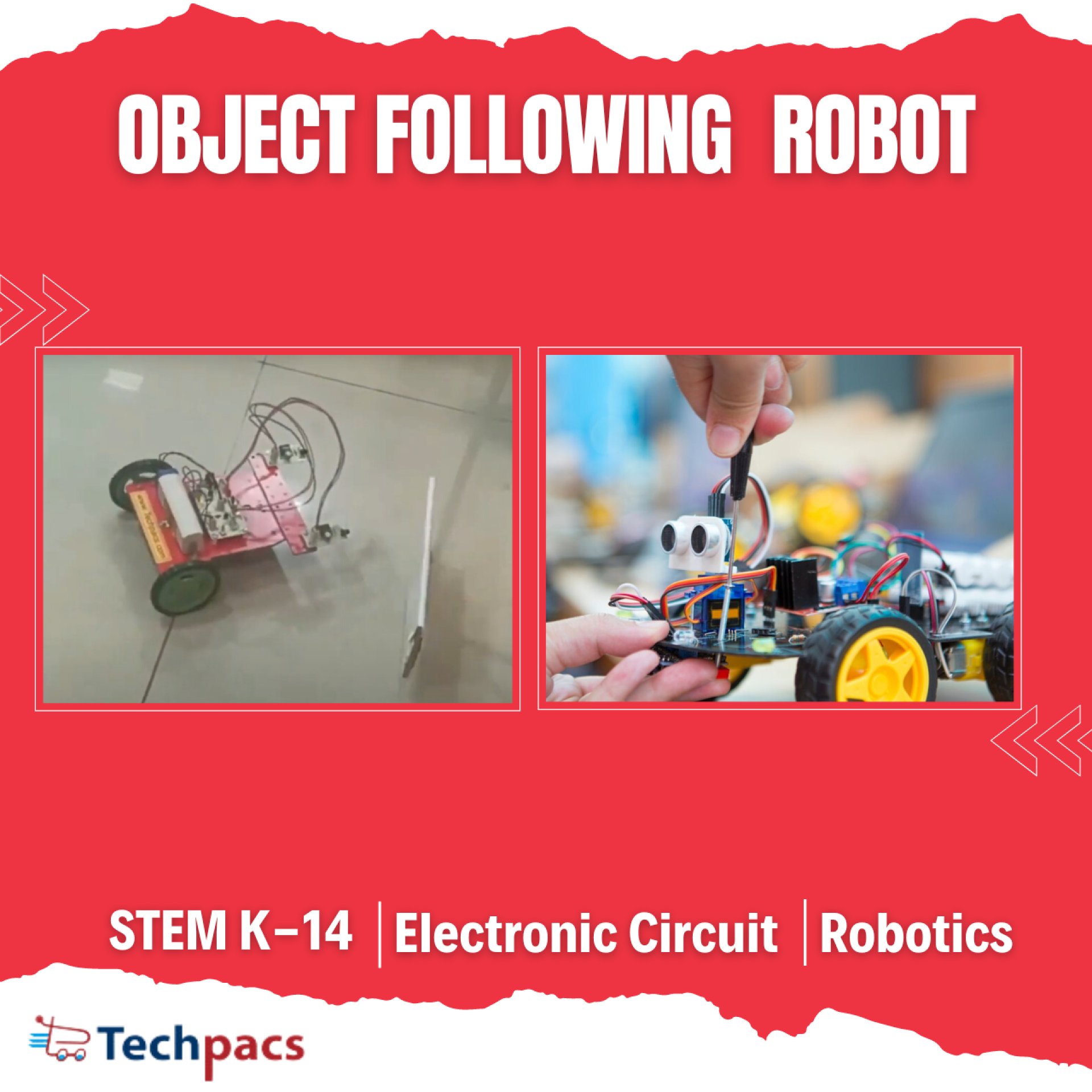

Object Following Robot for Educational Robotics Projects
The Object Following Robot project is aimed at developing an autonomous mobile robot that can track and follow a designated object using sensors and motor controls. This project is designed for educational purposes to help students and hobbyists learn about robotics, electronics, and programming. By integrating various components such as sensors, motors, and a microcontroller, the robot can detect and follow objects with a high degree of accuracy. This project not only fosters an understanding of fundamental robotics principles but also promotes hands-on learning experiences in the field of mechatronics and automation.
Objectives
To design and build an autonomous robot that can detect and follow objects.
To integrate sensors and motors effectively for responsive movement.
To program the microcontroller for object detection and movement algorithms.
To provide a hands-on educational tool for learning robotics and electronics.
To achieve efficient power management for prolonged usage.
Key Features
Autonomous object detection and following capability.
Integration of ultrasonic or infrared sensors for precise tracking.
Dual motor control for smooth and responsive movement.
Microcontroller-based design for flexible programming and control.
User-friendly design with expandable features for advanced projects.
Application Areas
The Object Following Robot project has several practical applications. In educational settings, it serves as an invaluable tool for teaching students about robotics, electronics, and programming through a hands-on approach. It can also be used in workshops and hobbyist projects to promote STEM learning. Additionally, this robot can be adapted for various real-world applications, such as automated guided vehicles (AGVs) in industrial settings, personal assistant robots in smart homes, and as a base platform for more advanced research in autonomous systems and artificial intelligence. Its versatility makes it a significant addition to any educational or research institution focused on robotics.
Detailed Working of Object Following Robot for Educational Robotics Projects
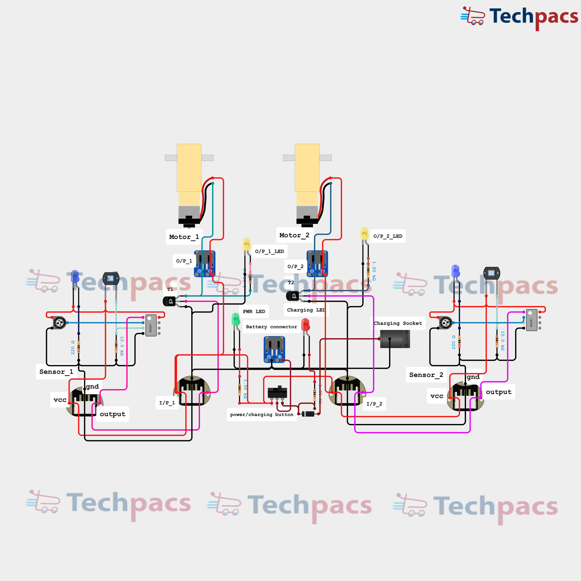
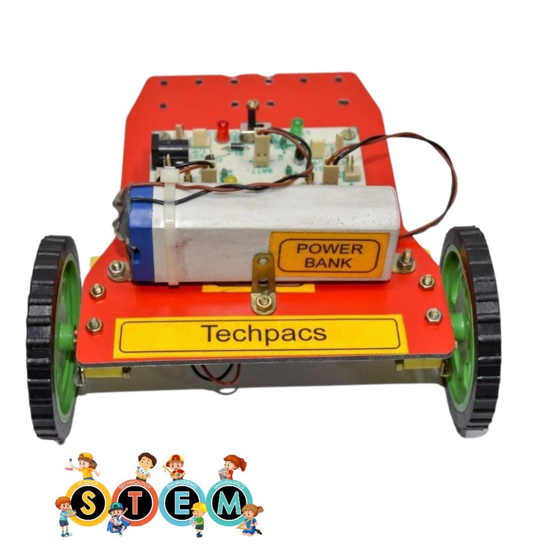
The object-following robot is an educational robotics project designed to combine various electronic components in an interactive way to demonstrate basic robotic and sensor principles. This project revolves around a circuit that seamlessly integrates numerous components, including sensors, motors, transistors, LEDs, and a power supply module, all working in concert to achieve object detection and movement following. Let's dive deeper into the working of this project to understand how such integration is achieved.
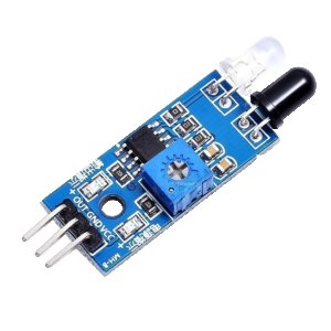
At the heart of this project are two key infrared sensors labeled Sensor_1 and Sensor_2. These sensors are tasked with detecting the presence of an object in their vicinity. The sensors generate output signals when they detect an object. Sensor_1 and Sensor_2 are powered by connecting their Vcc pins to a voltage supply and their GND pins to the ground. Their outputs are fed into two distinct inputs, I/P_1 and I/P_2, respectively. These inputs serve as gateways for transmitting the received signals further into the circuit.
The signals from the sensors trigger specific transistors, T1 and T2, which act as electronic switches. When an object is detected by Sensor_1, it sends a signal to input I/P_1, turning on transistor T1. Likewise, an object detected by Sensor_2 sends a signal to input I/P_2, which then turns on transistor T2. The activity of these transistors subsequently controls the state of the connected LEDs (O/P_1_LED and O/P_2_LED) to visually indicate the detection status.
Connecting the detected object signals to the movement mechanism, the transistors, in turn, drive two Motors, Motor_1 and Motor_2. The operation of these motors is directly influenced by the state of the transistors. When T1 or T2 is activated, it allows current to flow through the corresponding motor, causing it to run. This mechanization forms the core movement control of the robot, enabling it to follow the detected object. Motor_1 responds to Sensor_1 while Motor_2 responds to Sensor_2, with both motors executing coordinated movements based on the sensor inputs.
The power supply and control structure of this robotic circuit are paramount for its seamless operation. A power button, denoted as the power/charging button, is included for turning the entire setup on and off. The power input is facilitated through a battery connector, which ensures a consistent supply of voltage, distributed appropriately throughout the circuit. Additionally, a charging socket is provided to recharge the battery, ensuring continuous operation without manual battery replacement.
Visual indicators such as the PWR LED and Charging LED offer insight into the operation status of the robot. The PWR LED illuminates when the circuit is powered, while the Charging LED indicates the battery charging state. This feedback system is crucial for troubleshooting and ensures that the user is always aware of the current status and health of the robot's power system.
In summary, this educational object-following robot project intricately combines sensors, transistors, LEDs, motors, and power management components into a cohesive system. The primary workflow begins with object detection by infrared sensors, followed by signal amplification through transistors, and ultimately resulting in controlled motor movements. These movements allow the robot to adeptly follow objects, providing an engaging and interactive demonstration of electronic and robotic principles for students and enthusiasts alike.

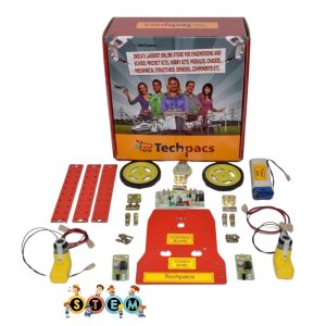
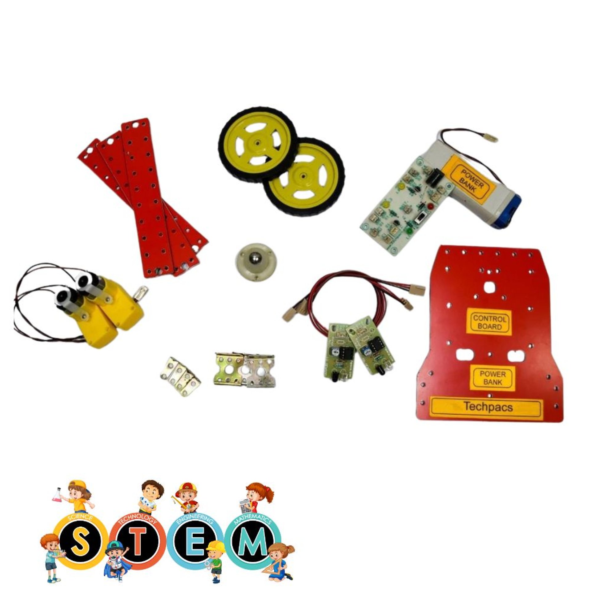
Modules used to make Object Following Robot for Educational Robotics Projects:
Power Supply Module
The power supply module is crucial as it provides the necessary electrical energy required for the operation of the robot. This module includes the battery connector, charging socket, and battery itself. The power button ensures the battery power is appropriately allocated to different components of the robot. When the power button is pressed, the battery delivers voltage to the circuit, activating the power LED indicator to signal that the circuit is live. Various wires branched out from this module distribute the power to sensors, motors, and the circuitry that controls the robot’s operation. Adequate power regulation is essential to ensure consistent performance and to prevent damage to sensitive components.
Control and Regulation Module
The control and regulation module plays a pivotal role in managing the overall function of the object-following robot. This module includes transistors T1 and T2, which act as electronic switches, controlling the current flow to the motors based on the signals received. When the sensors detect an object, they send output signals to the transistors. These signals are further processed to regulate the motors' speed and direction, ensuring the robot can follow the object accurately. The intricate wiring connections within this module ensure the synchronization of sensor inputs and motor outputs, leading to a well-coordinated movement of the robot. LEDs are used to provide visual feedback on the operation status.
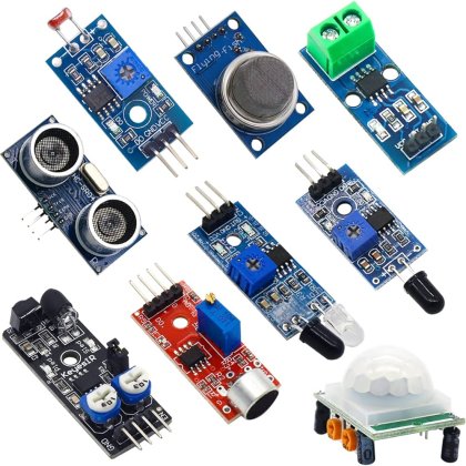
Sensor Module
The sensor module comprises two primary sensors, Sensor_1 and Sensor_2, placed strategically for optimal detection of objects. These sensors act as the robot's eyes, continuously scanning the surroundings for any object within their vicinity. Each sensor has its dedicated VCC (power), GND (ground), and output pins that feed data into the control module. When an object is detected, the corresponding sensor sends a signal through its output pin, which is then processed to determine the robot’s path. Proper alignment and synchronization of these sensors are critical to ensure accurate detection and effective object following. Indicators and resistors are utilized to manage the sensors’ power and signal integrity.
Motor Driver Module
The motor driver module is responsible for converting the signals from the control module into actual movement. This module includes Motor_1 and Motor_2, which are connected to the output pins from the transistors. When the transistors receive signals from the sensors, they control the flow of current to the motors, enabling movement. Motor_1 and Motor_2 work in coordination to steer the robot in the desired direction, thus enabling it to follow an object. The proper wiring between the motors and other circuit components is essential to avoid any latency or irregular movements. This module also includes LED indicators that provide visual cues about the motors' operational status.
Feedback and Indicator Module
The feedback and indicator module includes various LEDs that offer visual feedback on different statuses of the robot. There are indicators for power (PWR LED), charging (CHARGING LED), and motor outputs (O/P_1_LED and O/P_2_LED). These LEDs help in troubleshooting and ensure that each module is performing correctly. For instance, the PWR LED confirms the power supply is active, while the O/P LEDs indicate that the motors are receiving control signals. This module, thus, ensures real-time monitoring and quick diagnostic capabilities for educational purposes. Proper placement and connection of these LEDs are crucial for accurate feedback and effective learning outcomes.
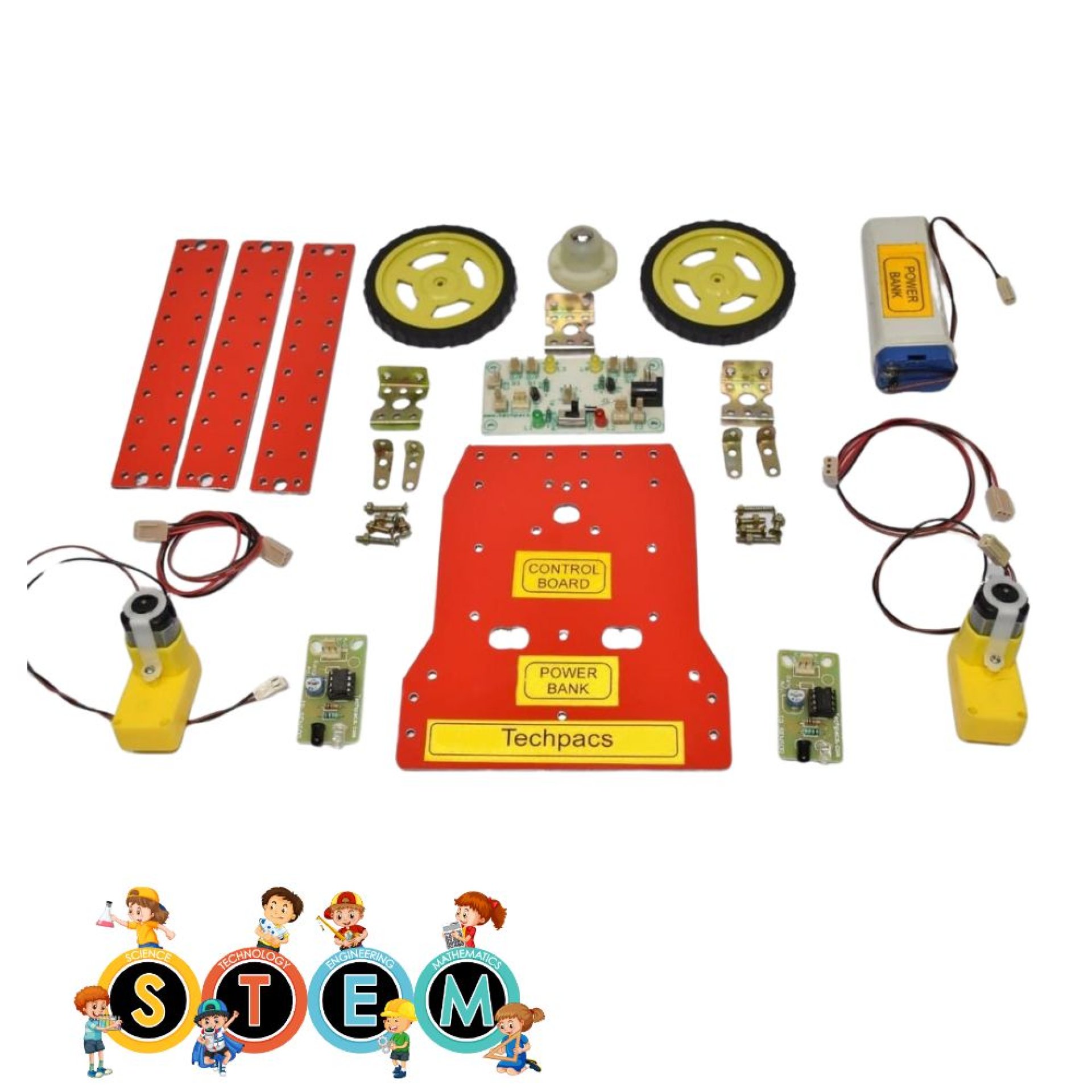
Components Used in Object Following Robot for Educational Robotics Projects :
Motors
Motor_1
Motor 1 is the primary driving force on one side of the robot, enabling it to move.
Motor_2
Motor 2 works alongside Motor 1 to propel the robot, providing the necessary torque.
Sensors
Sensor_1
Sensor 1 detects the presence and distance of objects, helping the robot to follow them.
Sensor_2
Sensor 2 works with Sensor 1 to enhance object detection and navigation accuracy.
LED Indicators
O/P_1_LED
Indicates the operational status of Motor 1 by lighting up when powered.
O/P_2_LED
Indicates the operational status of Motor 2 by lighting up when powered.
PWR_LED
Shows whether the robot's power supply is on or off, providing a visual power status.
Charging_LED
Indicates the charging status of the robot when connected to a power source.
Power Supply
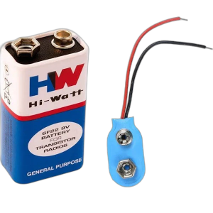
Battery Connector
Connects the battery to the robot's circuitry, supplying the necessary power for operation.
Charging Socket
Allows the robot's battery to be recharged by connecting it to an external power source.
Control Buttons
Power/Charging Button
Used to switch the robot on or off and controls its charging mode.
Miscellaneous Components
T1
Transistor 1 is used to amplify or switch electronic signals for Motor 1.
T2
Transistor 2 is used to amplify or switch electronic signals for Motor 2.
Other Possible Projects Using this Project Kit:
The provided circuit diagram showcases the essential components and connections required for constructing an object-following robot. Leveraging the same project kit, several other engaging and educational robotics projects can be developed. Here are a few alternatives:
1. Line Following Robot
By reconfiguring the same components present in the object-following robot kit, students can build a line-following robot. The principal modification involves adjusting the sensors to detect and follow a pre-defined line on the floor, usually marked with black tape on a white surface. The sensors continuously check the line's position, sending signals to the microcontroller, which, in turn, adjusts the motor speeds to keep the robot on track. This project aids in understanding sensor processing, motor control algorithms, and feedback loops, making it a valuable learning experience in robotics and control systems.
2. Obstacle Avoidance Robot
An obstacle avoidance robot is another excellent project that can be adapted from the same components. In this application, the sensors are utilized to detect obstacles in the robot's path. When an obstacle is detected, the microcontroller processes the sensor data and triggers the necessary actions, such as stopping, turning, or reversing the motor direction to evade the obstacle. This project emphasizes the principles of sensor integration, decision-making algorithms, and real-time processing, providing a comprehensive understanding of autonomous navigation systems.
3. Light Following Robot
With slight alterations to the sensor arrangement, the project kit can be used to create a light-following robot. This robot will use photoresistors or light-dependent resistors (LDRs) to detect light sources. The LDRs sense the intensity of light and send signals to the microcontroller, which adjusts the motor's speed and direction to move the robot towards the light. This project is ideal for understanding the concepts of light sensing, analog signal interpretation, and motor control in response to varying environmental conditions.
4. Maze Solving Robot
A more advanced application involves creating a maze-solving robot. Utilizing the sensors for detecting walls and paths, the robot can be programmed to navigate through a maze. Algorithms such as the right-hand rule or the left-hand rule can be employed to guide the robot’s movements. This project introduces learners to the concepts of pathfinding, decision making in constrained environments, and algorithmic thinking. It offers a deeper dive into coding, sensors optimization, and autonomous navigation.
5. Bluetooth Controlled Robot
By integrating a Bluetooth module into the existing project kit, students can create a robot that can be controlled via a smartphone or any Bluetooth-enabled device. The commands sent through a custom-built mobile application can be received by the Bluetooth module, which then instructs the microcontroller to drive the motors accordingly. This project provides a practical understanding of wireless communication, mobile application development, and real-time control, making it a contemporary project in the field of robotics.
| Shipping Cost |
|
No reviews found!


No comments found for this product. Be the first to comment!