


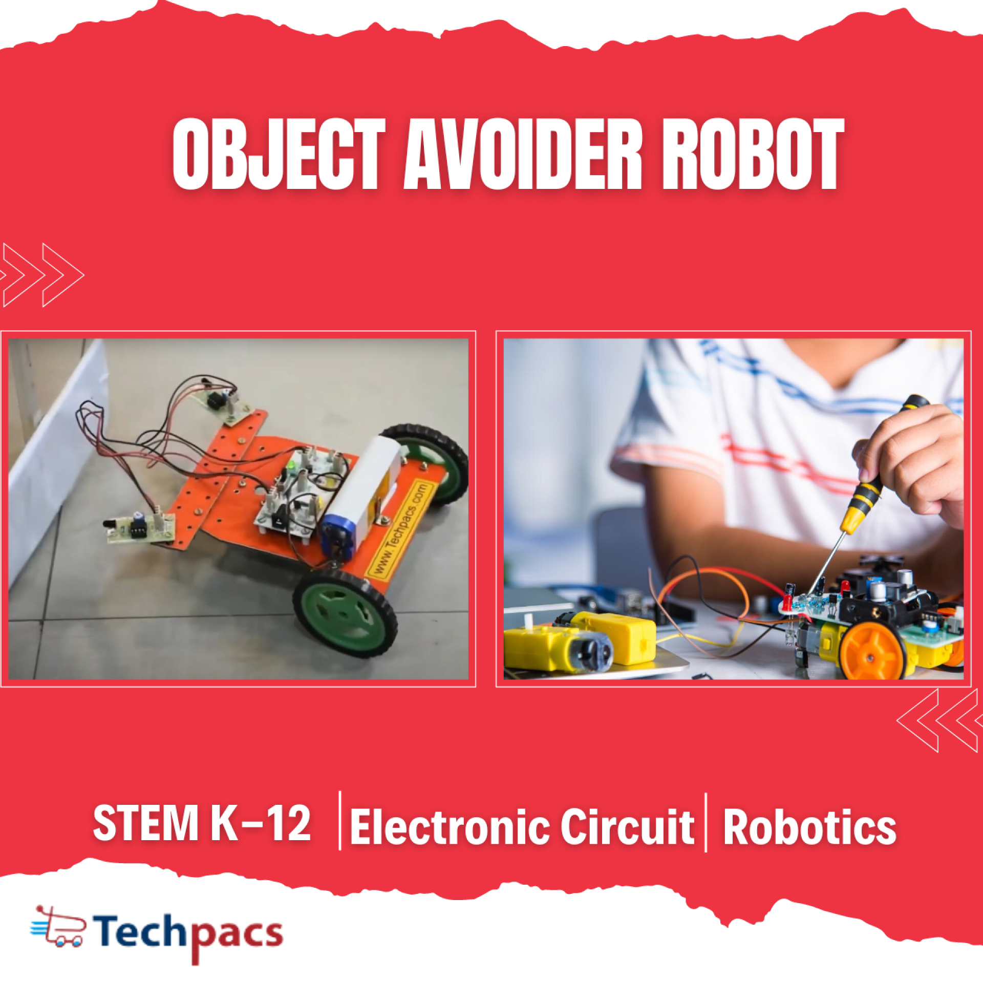
Object Avoider Robot for Detecting and Avoiding Obstacles
Robotics has been a continuously evolving field, making it possible to build intelligent machines that can perform a variety of tasks autonomously. The "Object Avoider Robot for Detecting and Avoiding Obstacles" project aims to create a robot that can detect obstacles in its path and navigate around them without human intervention. Utilizing sensors and microcontrollers, this robot interprets its surroundings and makes real-time decisions to avoid collisions. This technology can be applied in various fields, including domestic assistance, industry automation, and enhanced mobility for individuals with disabilities. This project will serve as a blueprint for developing more advanced autonomous machines.
Objectives
1. Develop a robotic system capable of detecting obstacles using sensors.
2. Implement an algorithm to interpret sensor data and make real-time navigation decisions.
3. Achieve seamless obstacle avoidance with minimum lag.
4. Ensure the robot can operate autonomously without human intervention.
5. Test and validate the robot's performance in different environments.
Key features
1. Real-time obstacle detection and avoidance.
2. Multiple sensor integration for enhanced perception.
3. Autonomous navigation without human intervention.
4. Rechargeable battery for extended operation.
5. Robust design for operation in various environments.
Application Areas
The Object Avoider Robot has numerous applications across different sectors. In the domestic sphere, it can help in household cleaning and assistive roles for the elderly or disabled individuals. Industrial automation can greatly benefit from such robots in tasks requiring navigation through cluttered environments, thus improving efficiency and safety. In the field of transportation, these robots can be utilized for unmanned deliveries or as autonomous vehicles in controlled environments like warehouses or factories. Additionally, research and educational institutions can use this robotic system to further studies in advanced robotics and artificial intelligence applications.
Detailed Working of Object Avoider Robot for Detecting and Avoiding Obstacles :
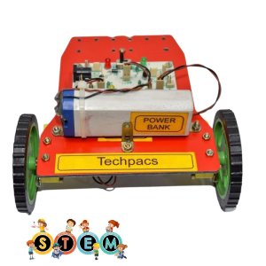
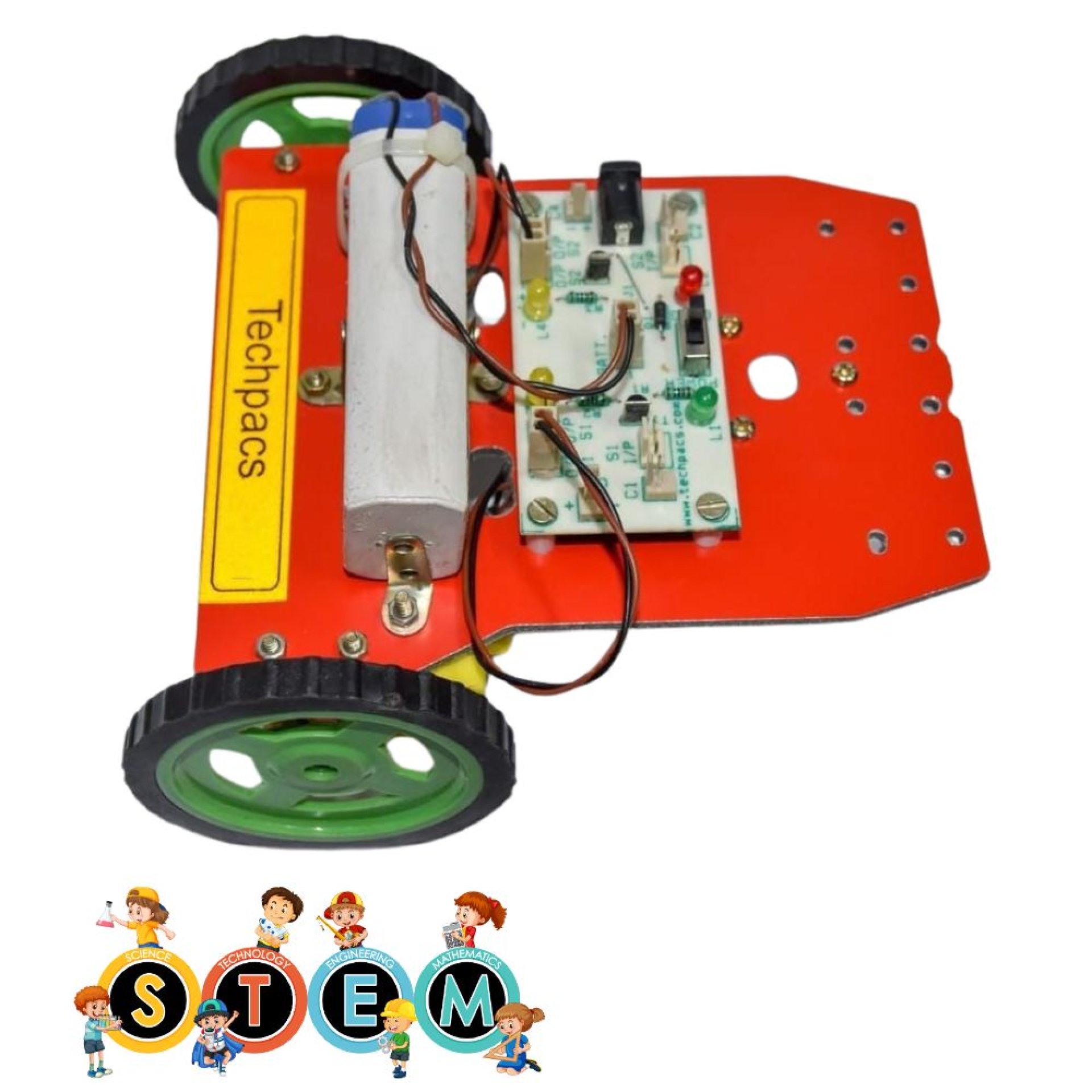
The Object Avoider Robot circuit is a marvel of modern technology, incorporating sensors, transistors, and motors to automate obstacle detection and evasion. The primary components of this circuit involve two IR sensors, two motors, transistors, and LEDs, all orchestrated to ensure the robot can navigate its environment without colliding with obstacles. The heart of this system revolves around the effective collaboration between these components, creating a seamless flow of data and actions to achieve precise navigation.
At the core of this system is the IR sensors (Sensor_1 and Sensor_2), mounted at the front of the robot. These sensors constantly emit infrared light and detect any reflections caused by nearby obstacles. When an obstacle is within the sensor's detection range, the infrared light reflects back to the sensor. The sensors have output pins connected to transistors T1 and T2 which help in switching the motors.
The output from Sensor_1 is connected to the base of transistor T1. Similarly, the output from Sensor_2 is connected to the base of transistor T2. When Sensor_1 detects an obstacle, it sends a signal to T1, activating it. This allows current to flow through T1, powering Motor_1. Likewise, when Sensor_2 detects an obstacle, it activates transistor T2, allowing current to flow through T2 and powering Motor_2. This mechanism creates a direct and immediate response to obstacle detection, ensuring the robot can react swiftly to changing environments.
The motors (Motor_1 and Motor_2) are the drive mechanisms of the robot. They are connected to both the wheels and the transistors. When there is no obstacle, Sensor_1 and Sensor_2 do not send active signals, thus keeping T1 and T2 turned off. This allows the motors to run normally, propelling the robot forward. However, when an obstacle is detected, the respective sensor activates the corresponding transistor, momentarily adjusting the motor's behavior to avoid the obstacle. For example, if Sensor_1 detects an obstacle, it activates T1, which in turn might reduce the speed or change the direction of Motor_1, enabling the robot to steer away from the obstacle.
An additional layer of feedback is provided by the LEDs labeled O/P_1_LED and O/P_2_LED, which are connected to the transistors T1 and T2. These LEDs light up when their respective transistors are activated, providing a clear visual indication of obstacle detection and avoidance in real-time. This visual feedback is crucial during the debugging phase and for a clear understanding of the robot’s interaction with its environment. The PWR_LED and Charging_LED provide indications for power and charging, ensuring the operator remains informed about the robot’s operational status at all times.
The power management in this circuit is handled by a battery connector and a power/charging button, which allow the robot to be powered on and off and facilitate easy recharging of the batteries. The charging socket is connected to the charging LEDs, indicating the charging status of the battery. This ensures that the robot remains operational for extended periods without power interruptions.
In conclusion, the Object Avoider Robot operates through a sophisticated interplay of sensors, transistors, and motors, all managed by a central battery source. As the sensors detect obstacles, they send signals to the transistors, which adjust the motor operations to navigate away from the obstacles efficiently. LEDs provide real-time feedback on obstacle detection and power status, enhancing the user’s ability to monitor the robot’s functionality. This intricate yet efficient circuit design ensures the robot can autonomously navigate its environment, avoiding obstacles with precision and reliability.
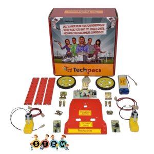
Modules used to make Object Avoider Robot for Detecting and Avoiding Obstacles:
1. Power Supply Module
The power supply module is central to the functioning of the Object Avoider Robot. It starts with a battery connector, linking the primary power source, which is usually a rechargeable battery, to the circuit. The charging socket is included to allow the battery to be recharged without disassembling the robot. A charging LED indicates the battery’s charging status, while a power LED shows when the robot is powered on. The power/charging button allows you to toggle between charging mode and operational mode. Power supply lines (red for positive and black for ground) are distributed across the entire circuit, ensuring that every component gets the necessary power to function.
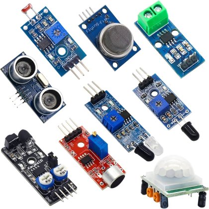
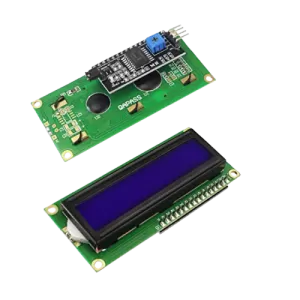
2. Sensor Module
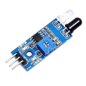
The sensor module plays a crucial role in detecting obstacles in the path of the robot. This project uses two sensors, labelled as Sensor_1 and Sensor_2 in the diagram. Each sensor typically comprises an ultrasonic sensor circuit. The sensors have three pins: Vcc (power), GND (ground), and Output. Vcc is connected to the power supply module, while GND is connected to the ground. The output pin is connected to an input control module, which allows it to send data regarding obstacles detected in the environment. These sensors emit ultrasonic waves and measure the time taken for the waves to bounce back from any obstacles, which is then used to determine the distance of the object from the sensor.
3. Input Control Module
The input control module processes the signals received from the sensor module. It is represented by the labels I/P_1 and I/P_2 on the circuit diagram. These inputs are received from the output pins of Sensor_1 and Sensor_2. The module’s job is to interpret the data – if the sensor detects an obstacle at a certain distance, the input control module will send control signals to the motor driver module to adjust the robot's direction. Essentially, this module acts as the brain of the robot, deciding when and how to move based on the sensor readings.
4. Motor Driver Module
The motor driver module translates the low-power control signals from the input control module into high-power signals that can drive the motors. It includes Motor_1 and Motor_2, each connected to motor drivers labelled T1 and T2. These transistors amplify the control signals to the level required by the motors. The motor driver module's main task is to control the direction and speed of each motor based on the signals it receives. If Sensor_1 detects an obstacle on the left, the input control module will command the motor driver to steer the robot to the right by adjusting the speed or direction of Motor_1 and Motor_2 accordingly.
5. Indicator Module
The indicator module provides visual feedback about the status of the robot. This includes several LEDs: PWR_LED to show the power status, Charging_LED to show the battery charging status, and other status LEDs connected to T1 and T2 to show the activity or error status of Motor_1 and Motor_2. These LEDs help in debugging and monitoring the robot's operation in real-time. For example, if the charging LED is on, the user knows that the robot is in charging mode and not ready for operation.
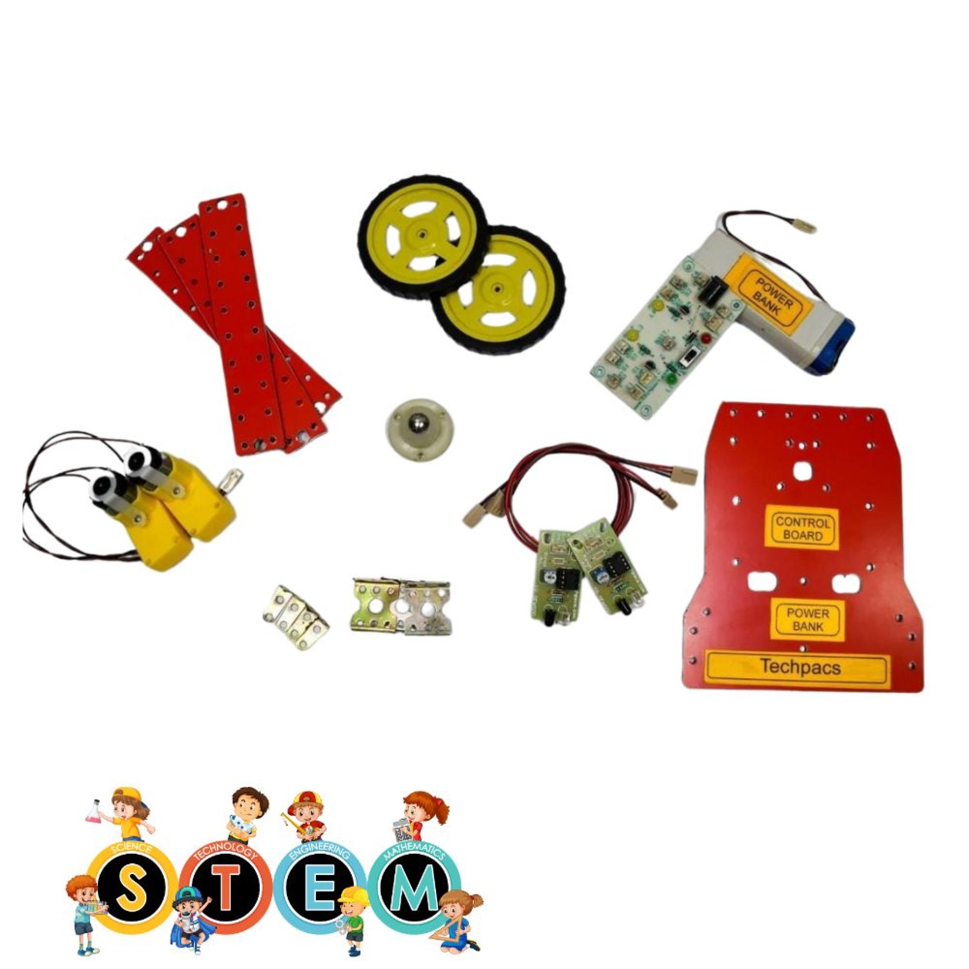
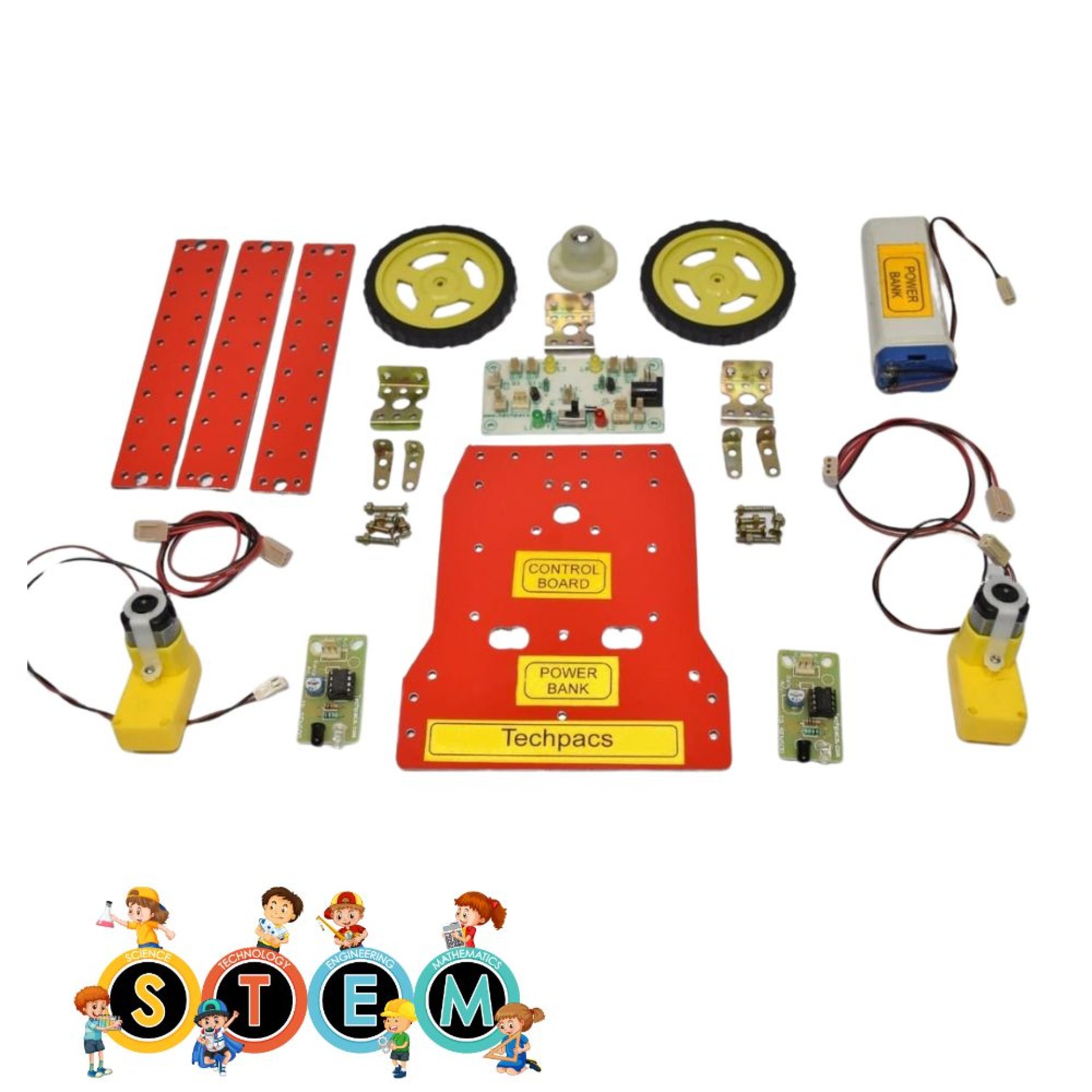
Components Used in Object Avoider Robot for Detecting and Avoiding Obstacles :
Sensors Module
Sensor_1: This sensor detects obstacles in front of the robot. It's crucial for sending signals to the control system to stop or change the robot's direction when an obstacle is detected.
Sensor_2: This sensor detects obstacles on another path. It ensures the robot can avoid objects on multiple sides for smoother navigation.
Power Module
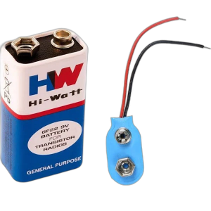
Battery Connector: This component connects the power source to the entire circuit, providing necessary energy to all modules.
Charging Socket: Allows for easy recharging of the robot's battery, ensuring the system remains operational without frequent battery replacement.
Power/Charging Button: This button switches the robot between operational mode and charging mode, ensuring control over power usage.
Indicator LED Module
PWR LED: Indicates when the robot is powered on. This helps in checking if the power circuit is functioning correctly.
Charging LED: Shows the status of the charging process. Helps in determining if the battery is being charged correctly.
O/P 1 LED: Indicates the output signal from Sensor 1, showing whether an obstacle is detected.
O/P 2 LED: Indicates the output signal from Sensor 2, showing the presence of an obstacle detected by Sensor 2.
Motor Driver Module
Motor_1: Rotates to drive one side of the robot. It helps in movement and changing direction when avoiding obstacles.
Motor_2: Drives the opposite side of the robot, ensuring coordinated movement and smooth turning capability.
Transistor Module
T1: Acts as a switch, controlling the current to Motor 1 based on signals from Sensor 1.
T2: Controls the current to Motor 2, switching it on/off according to signals from Sensor 2.
Input Module
I/P_1: Input point receiving signals from Sensor 1 to process and trigger Motor 1 operation.
I/P_2: Receives signals from Sensor 2 to process and control Motor 2, enabling obstacle avoidance actions.
Other Possible Projects Using this Project Kit:
1. Line Following Robot
Using the same components from the object avoider robot, a line following robot can be constructed. This robot will follow a predetermined path, often marked by a black line on a white surface or vice versa. The infrared (IR) sensors used in the object avoider can be reprogrammed to detect the contrast between the line and the background. The motors and the motor driver circuit will control the robot’s movement, enabling it to follow the path accurately. Such a robot can be utilized in industrial settings for automated material transport or can be a great demonstration tool for beginners learning about robotics and sensor integration.
2. Automated Wall Following Robot
With modifications, the object avoider robot can be transformed into a wall following robot. This type of robot navigates by maintaining a constant distance from a wall or barrier, which can be useful for mapping environments or in situations where it needs to navigate a maze. By strategically placing the IR sensors on the side of the robot and implementing appropriate programming logic, the robot can measure its distance from the wall and adjust its path accordingly. This helps in understanding ultrasonic and IR sensor applications in real-life navigation and robotics.
3. Automatic Light Seeking Robot
Another interesting application is an automatic light-seeking robot, which uses the same motor and sensor setup but with light-dependent resistors (LDRs) as sensors. The robot would move towards a light source, which can be beneficial in situations where it needs to locate a docking station equipped with a light signal for charging. This kind of robot demonstrates the principles of phototaxis (movement towards light) and can be a fascinating project for demonstrating basic robotics and automated systems in classrooms or competitions.
4. Path Finding Robot Using Search Algorithms
Utilizing the components from the object avoider robot kit, a path finding robot can be designed to navigate its way to a target using search algorithms like A* or Dijkstra’s algorithm. This project will involve integrating additional sensor technologies such as ultrasonic sensors for better environmental mapping. The robot not only avoids obstacles but also finds the shortest path to its destination, enhancing its applicability in complex and dynamic environments like search and rescue operations or automated delivery systems inside buildings. This provides a deeper understanding of algorithmic navigation and advanced robotics.
5. Gesture Controlled Robot
By incorporating a gesture recognition module (like an accelerometer-based glove or a camera with gesture recognition software) along with the existing components, the kit can be used to create a gesture-controlled robot. The motors and motor driver circuits can be connected to a microcontroller that receives input from the gesture module, allowing users to control the robot’s movements with hand gestures. This type of robot can be applied in interactive robotics for educational purposes, showcases in tech exhibitions, or even assistive technology for people with motor impairments.
| Shipping Cost |
|
No reviews found!


No comments found for this product. Be the first to comment!