


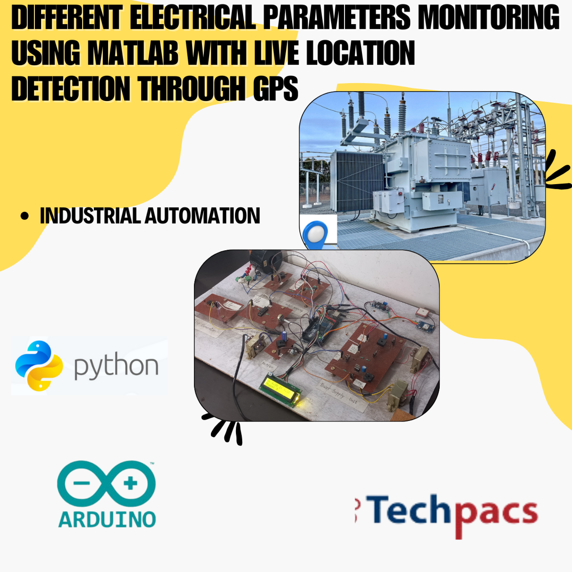
Arduino-Based System for Monitoring Electrical Parameters with MATLAB and GPS
The Arduino-Based System for Monitoring Electrical Parameters with MATLAB and GPS is a comprehensive project designed to measure and analyze key electrical parameters in real-time. This system leverages the power of Arduino for data acquisition and integrates MATLAB for data processing and visualization. An added GPS module provides location data, making this system versatile for applications requiring geographical context. The system is particularly suited for monitoring environments where precise and real-time data on electrical consumption and performance is critical. This system aims to improve efficiency, ensure safety, and support maintenance operations by providing detailed insights into electrical parameters.
Objectives
- To measure electrical parameters such as voltage, current, and power in real-time.
- To visualize the collected data using MATLAB for advanced analysis.
- To incorporate GPS data for associating electrical parameters with geographical locations.
- To improve the efficiency and safety of electrical systems through continuous monitoring.
- To facilitate proactive maintenance by providing detailed electrical performance insights.
Key Features
- Real-time monitoring of voltage, current, and power using Arduino.
- Integration with MATLAB for data processing and visualization.
- GPS module to provide geographical context to the electrical parameters.
- LCD display for local real-time data viewing.
- Data logging for historical analysis and trend identification.
- Customizable threshold alerts for abnormal electrical conditions.
- User-friendly interface for ease of setup and use.
Application Areas
The Arduino-Based System for Monitoring Electrical Parameters with MATLAB and GPS is suitable for a wide range of applications. It can be used in industrial environments to monitor machinery and equipment, ensuring they operate within safe electrical parameters. This system is also valuable in residential settings for monitoring household energy consumption, helping homeowners reduce energy costs and enhance safety. In the research field, it supports experiments and studies requiring detailed electrical data analysis. Additionally, the integration of GPS functionality makes it ideal for mobile and remote installations, offering insights into electrical usage and performance in vehicles, outdoor equipment, and infrastructure projects. This system's adaptability and comprehensive monitoring capabilities make it invaluable across various sectors.
Detailed Working of Arduino-Based System for Monitoring Electrical Parameters with MATLAB and GPS :
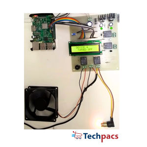
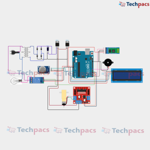
The Arduino-Based System for Monitoring Electrical Parameters with MATLAB and GPS is designed to measure, display, and log various electrical characteristics while concurrently providing real-time geolocation data. This detailed description will walk you through how the circuit operates, capturing and translating electrical parameters into insightful data, which is then interpreted and presented by MATLAB and GPS module.
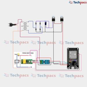
Our journey begins with a 220V AC main supply which is stepped down to 24V AC using a transformer. This stepped-down AC voltage is further rectified by a bridge rectifier circuit. The rectified DC voltage is then filtered using a capacitor to provide a steady DC output. To achieve regulated voltages, the rectifier's output is fed into two voltage regulator ICs, the 7812 and 7805, which produce 12V and 5V DC outputs respectively. These regulated voltages are crucial as they power the various components used in our system, ensuring they function correctly and protect them from voltage fluctuations.
The heart of the circuit is the Arduino Mega microcontroller which acts as the brain of the project. All the sensors and modules are interfaced with this microcontroller. Connected to the Arduino are the sensors which measure the voltage, current, and power used by the external load, in this case, a bulb. The voltage sensor module detects the voltage across the load, converting it to a readable value for the Arduino. The current sensor module measures the current flowing through the load, again providing a readable value to the Arduino. These two readings are used to calculate power consumption by the load.
Additionally, a GPS module is connected to the Arduino which logs the geographical location data. The GPS module continuously feeds real-time location data to the Arduino, which processes and sends this information along with the electrical parameters to MATLAB. This coupling of electrical data with precise location data provides a comprehensive overview of where and how the power is being used.
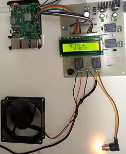
A 16x2 LCD display is also incorporated into the system to provide real-time feedback to the user. This display shows live readings of the electrical parameters, such as voltage, current, and power, giving immediate, on-location insight. The potentiometer linked to the LCD screen is used to adjust the display contrast, ensuring readability in various lighting conditions.
The Arduino continuously reads the sensor data and processes it. For instance, the analog values from the sensors are converted to corresponding voltage and current values using predefined calibration factors. These values are then used to compute the power consumption using the formula:
Power (Watts) = Voltage (Volts) x Current (Amperes)
All this data, once processed, is sent to a connected computer running MATLAB. MATLAB acts as a data logger and analysis tool, storing the incoming data and providing detailed analysis and visualizations of the power usage over time. This information is crucial for optimizing power consumption and identifying usage patterns.
Lastly, the GPS functionality amplifies the utility of this system significantly, making it especially useful in mobile or distributed systems where knowing the exact location of power usage is critical. The GPS and power data fusion can be utilized in various applications like smart grids, remote monitoring systems, and other advanced power management solutions.
In summary, the Arduino-Based System for Monitoring Electrical Parameters with MATLAB and GPS is an intricate network of components working harmoniously. The project's design ensures that electrical parameters are accurately measured and logged, while MATLAB processes these data to offer insights. Simultaneously, the GPS module provides real-time location monitoring, making this system a comprehensive tool for advanced electrical parameter monitoring and analysis.
Modules used to make Arduino-Based System for Monitoring Electrical Parameters with MATLAB and GPS :
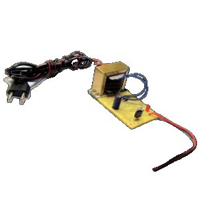
1. Power Supply Module
The power supply module is essential for providing a stable power source to the entire system. In this project, a step-down transformer is used to convert the high voltage (220V AC) to a lower voltage (24V AC). The rectifier circuit then converts this AC voltage to DC voltage, which is then smoothed by a capacitor. Voltage regulators are used to ensure the exact voltage levels required by different components: 12V and 5V. The regulated DC voltage is then distributed to all components including the Arduino Mega, sensors, and display modules. This ensures stable and consistent operation of all the components in the circuit.
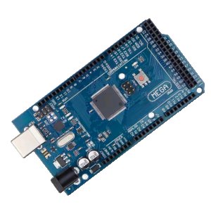
2. Arduino Mega
The Arduino Mega serves as the central processing unit for the project. It collects data from various sensors such as the current sensor and voltage sensor connected to it. These inputs are processed and the information is then used to execute control algorithms. It interfaces with the LCD display to show real-time data, and also communicates with the GPS module and the MATLAB interface via serial communication. The Arduino uses its digital and analog I/O pins to interact with the components, reading sensor values and controlling output devices accordingly.
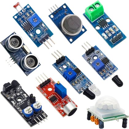
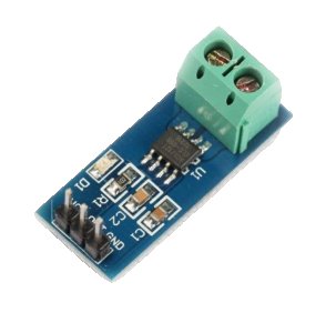
3. Sensing Module
The sensing module includes both voltage and current sensors to monitor electrical parameters. The current sensor measures the current flowing through the circuit, while the voltage sensor measures the voltage. These sensors are analog devices that provide continuous data to the Arduino Mega. The Arduino reads these values through its analog input pins, and processes this information to calculate parameters like power consumption. This data is essential for understanding the electrical characteristics of the system and for making any necessary adjustments or optimizations.
4. GPS Module
The GPS module is used to provide location data for the system. It communicates with the Arduino Mega via serial communication (TX and RX pins). The GPS module receives signals from satellites and calculates the current geographic location in terms of latitude and longitude. The Arduino reads this data and can either display it on the LCD screen or send it to MATLAB for further processing. This is particularly useful for mobile systems where the location needs to be tracked along with electrical parameters.
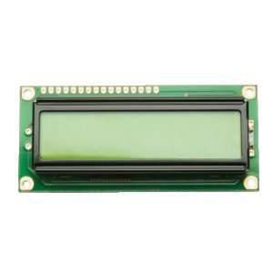
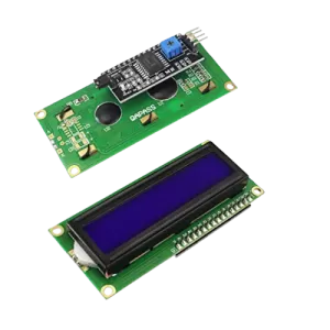
5. Display Module
The display module consists of an LCD screen connected to the Arduino Mega. This module is used for real-time display of electrical parameters such as voltage, current, power consumption, and location data from the GPS module. The LCD is interfaced with the Arduino using parallel communication, which includes multiple data lines and control lines. The Arduino sends formatted data to the LCD, which then updates the displayed information. This allows users to easily monitor the system's status without needing to connect to a computer.
6. MATLAB Interface
The MATLAB interface is used for advanced data analysis and visualization. The Arduino Mega sends the collected data to MATLAB via serial communication. MATLAB scripts can be written to read this data, process it, and generate graphical representations of the electrical parameters over time. Additionally, MATLAB can be used to perform complex calculations, generate reports, and even control the Arduino remotely. This integration allows for a more in-depth analysis of the electrical system and can be used to develop more sophisticated monitoring algorithms.
Components Used in Arduino-Based System for Monitoring Electrical Parameters with MATLAB and GPS :
Power Supply Module
Transformer
Steps down the main voltage (220V) to a lower voltage (24V) suitable for the system.
Rectifier Diodes
Converts the AC voltage from the transformer into a pulsating DC voltage.
Smoothing Capacitor
Smooths out the pulsating DC output from the rectifier to reduce voltage variations.
Voltage Regulators (LM7812 and LM7805)
Provides stable 12V and 5V DC outputs to power different components in the circuit.
Measurement Module
Current Sensor
Measures the current flowing through the load and provides an output proportional to the current value.
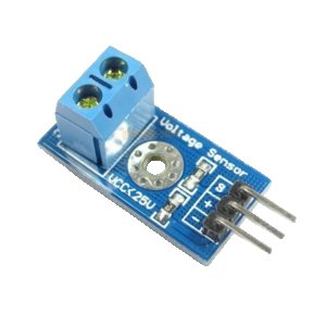
Voltage Sensor
Measures the voltage across the load and gives a corresponding output to the Arduino.
Microcontroller Module
Arduino Mega
Acts as the central processing unit, collecting data from sensors and processing it to send to MATLAB and GPS.
Display Module
LCD Display
Displays the measured electrical parameters and other information to the user.
Potentiometer
Adjusts the contrast of the LCD display for better readability.
GPS Module
GPS Module
Provides geographical location data to be sent along with the electrical parameters to MATLAB for analysis.
Other Possible Projects Using this Project Kit:
Home Automation System with Electrical Parameter Monitoring
Using the existing Arduino-based system, a home automation system can be developed. This enhanced project would allow users to remotely control home appliances such as lights, fans, and other electrical devices through a smartphone app or a web interface. The integration of the electrical parameter monitoring system will provide real-time feedback on energy consumption, allowing users to make informed decisions to save energy. Additional sensors can be incorporated to monitor conditions like temperature, humidity, and air quality, making the system an all-in-one solution for a smart home environment.
Smart Metering System
Develop a smart metering system that utilizes the Arduino and associated sensors to measure power consumption on a real-time basis. This project could further integrate GSM or Wi-Fi modules to send consumption data to a central server at predefined intervals. The data can be accessed through a web dashboard, providing users with historical consumption trends and alerts about unusual patterns. The GPS module can be used to ensure meter data is accurately tagged with location information, useful for distributed utility management and billing.
Industrial Machine Health Monitoring System
By modifying the existing system for industrial applications, it is possible to create a machine health monitoring system. This system can track parameters such as voltage, current, power factor, and more, giving insights into the performance and health of industrial machinery. Real-time alerts can be sent to maintenance teams if any parameters fall outside of predefined thresholds, helping to prevent machinery failures and reduce downtime. The integration with MATLAB allows for in-depth data analysis and predictive maintenance.
Renewable Energy Monitoring System
Utilize the project kit to monitor and manage renewable energy sources like solar panels and wind turbines. The Arduino can interface with current and voltage sensors to monitor the output and efficiency of renewable energy systems in real-time. GPS data can provide precise location tagging for performance analysis relative to geographic variables. The data can also be fed into MATLAB for comprehensive analysis and visualization, helping optimize energy production and storage strategies.
Electric Vehicle Charging Station Monitoring System
Design a monitoring system for electric vehicle (EV) charging stations. The Arduino board can be employed to track electrical parameters during the charging process, ensuring safety and efficiency. Real-time data on parameters like voltage, current, and power can be displayed on the LCD screen, while GPS data helps keep track of the location of different charging stations. Enhanced by MATLAB, this data can be analyzed for usage patterns, helping improve the infrastructure of EV charging networks, optimizing charging times and predicting maintenance needs.
| Shipping Cost |
|
No reviews found!


No comments found for this product. Be the first to comment!