


Temperature-Based Fan Control System for Improving Energy Efficiency
In an age where energy efficiency is paramount, the temperature-based fan control system offers a valuable solution. This project focuses on automatically adjusting the fan speed based on the surrounding temperature, providing an efficient means of managing energy consumption. By integrating sensors and control circuitry, the system ensures that fans operate only when necessary, reducing wasteful energy usage in household and industrial environments. The project leverages affordable components and straightforward assembly, making it accessible and feasible for widespread implementation.
Objectives
To develop a system that automatically adjusts fan speed based on ambient temperature.
To achieve energy efficiency by minimizing unnecessary fan operation.
To reduce energy costs for users by optimizing fan usage.
To provide a scalable and adaptable solution for different environments.
To ensure ease of implementation and low-cost production.
Key Features
Automatic temperature-based fan speed control.
Energy-efficient operation reducing power wastage.
Integration with affordable and readily available components.
User-friendly interface for easy setup and monitoring.
Adaptable for various applications in both residential and industrial settings.
Application Areas
The temperature-based fan control system is versatile and can be applied in multiple areas. In residential settings, it can be used to control ceiling and exhaust fans to improve comfort and reduce energy costs. In industrial environments, the system can manage cooling fans for machinery and electronic equipment, thereby enhancing operational efficiency and prolonging the lifespan of devices. Additionally, it can be implemented in data centers to optimize cooling operations, ensuring server stability while minimizing power consumption. Public facilities and offices can also benefit by maintaining consistent air circulation and temperature control, thereby improving comfort for occupants.
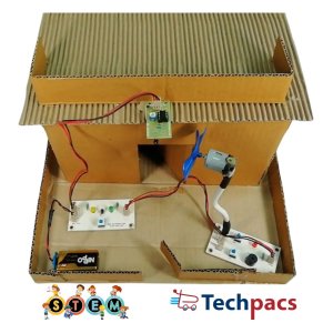
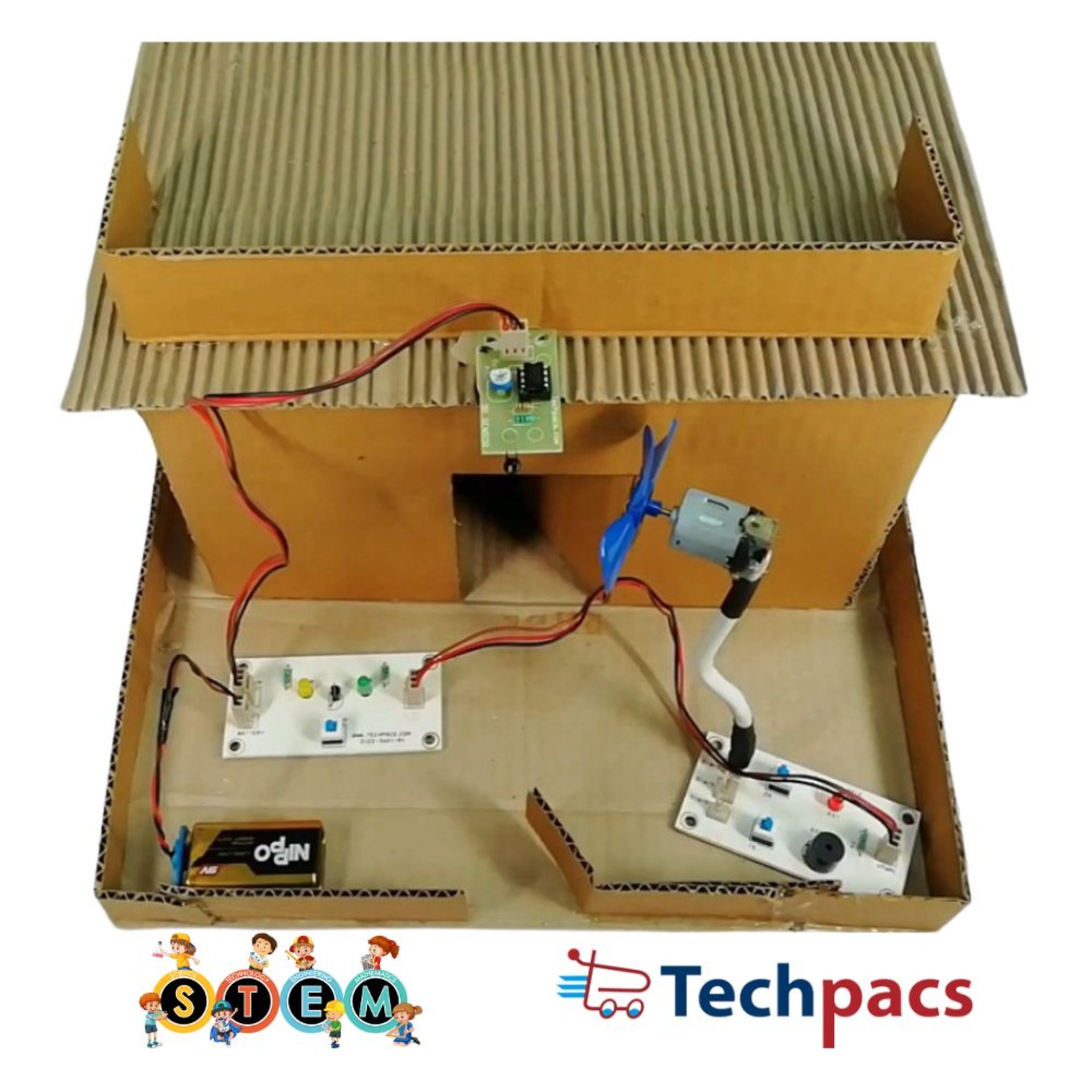
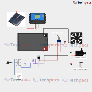
Detailed Working of Temperature-Based Fan Control System for Improving Energy Efficiency :
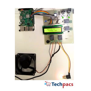
The temperature-based fan control system is an innovative circuit designed to adjust the speed of a fan automatically based on the surrounding temperature. The primary objective of this system is to enhance energy efficiency by running the fan only when necessary and at an appropriate speed, thereby conserving energy without compromising comfort.
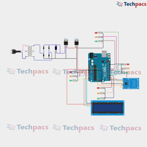
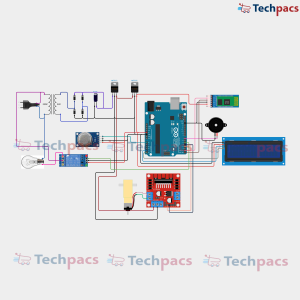
At the heart of this circuit lies the thermistor, a temperature-sensitive resistor whose resistance changes with temperature variations. The thermistor is connected to the I/O Connector, forming a voltage divider with a fixed resistor. This configuration generates a temperature-dependent voltage signal, which is fed into the analog input of a microcontroller. The microcontroller is the brain of the system, programmed to monitor this voltage continuously and to interpret it as a temperature value.
The microcontroller is powered by a 9V battery, ensuring the system operates independently of the main power supply. The battery is connected through a battery connector, which also ensures proper polarity. Once powered, the microcontroller initializes and starts reading the voltage from the thermistor. Based on the pre-programmed logic, it determines the current temperature and decides if the fan needs to be turned on and at what speed.
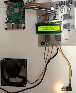
The microcontroller then sends a control signal to a relay module connected to the O/P Connectors. This relay acts as a switch, allowing a higher power circuit to be controlled by the low power signal from the microcontroller. The relay, in turn, controls the power supply to the DC motor, which drives the fan. Depending on the temperature, the microcontroller can adjust the voltage supplied to the motor, varying the fan speed accordingly.
In addition to controlling the fan, the circuit includes an LED and a buzzer connected to the respective O/P Connectors. These components provide visual and auditory feedback on the system's status. For instance, the LED can indicate when the fan is running, giving a visual representation of the system's operation. The buzzer can be programmed to emit a sound if the temperature exceeds a certain threshold, alerting users to potentially hazardous conditions that need attention.
Every time the user adjusts the fan speed manually or if the system detects a change in temperature, the microcontroller processes this information and updates the fan's status accordingly. This continuous feedback loop ensures the fan operates at an optimal speed, conserving energy while maintaining environmental comfort. Moreover, this dynamic adjustment helps prolong the fan motor's lifespan by avoiding unnecessary running at full speed when not needed.
Overall, the temperature-based fan control system is a sophisticated and energy-efficient solution for climate control. By leveraging a thermistor's properties, a microcontroller's processing power, and relay control, the system ensures that the fan operates only when beneficial, enhancing energy efficiency and contributing to reduced electrical consumption. This innovative approach exemplifies how modern electronics can provide smarter and more sustainable solutions for everyday applications.
Modules used to make Temperature-Based Fan Control System for Improving Energy Efficiency :
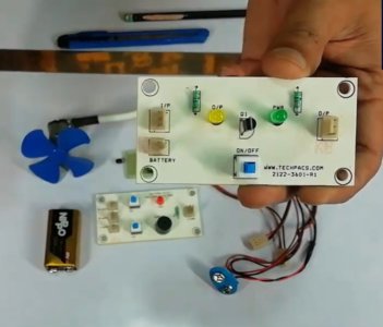
1. Power Supply Module
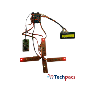
The power supply module is the backbone of the Temperature-Based Fan Control System. In the provided circuit, a 9V battery serves as the power source, delivering necessary electrical power to all components. This module includes battery connectors, and sometimes a voltage regulator if different voltage levels are needed for specific components. The voltage from the 9V battery is distributed to the various modules - the thermistor, operational amplifier (Op-Amp), fan, buzzers, LEDs, and relay via the power tracks. This module ensures a stable and continuous power flow, preventing disruptions that can affect the signal processing or actuation of the fan.
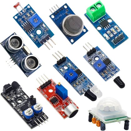
2. Sensor Module
The sensor module primarily consists of a thermistor, a type of resistor whose resistance varies with temperature. In this system, the thermistor detects ambient temperature changes. The thermistor is connected to the circuit in such a way that changes in temperature result in corresponding changes in voltage across the sensor. This voltage variation serves as the input signal, representing the current temperature. Proper placement and calibration of the thermistor are crucial for accurate temperature readings. The analog signal from the thermistor is then fed into the signal processing module.
3. Signal Processing Module
The signal processing module enhances and interprets the signal received from the sensor. It typically involves an Operational Amplifier (Op-Amp) that amplifies the small voltage changes from the thermistor. This amplification is vital for ensuring that the subsequent modules can clearly interpret the temperature signal. The Op-Amp may also compare the thermistor voltage against a reference voltage, producing a digital output that signifies whether the temperature is above or below the threshold. This processed signal, now a clear representation of temperature data, is then sent to the control module to determine the appropriate action.
4. Control Module
The control module, often a relay in this circuit, handles the decision-making based on the input signal from the signal processing module. When the processed signal indicates that the temperature has reached a certain threshold, the relay actuates, acting as a switch to control the flow of current to the fan. The relay ensures that the fan gets activated precisely when needed, thus reducing unnecessary energy consumption. Additionally, the relay's ability to handle higher currents ensures that the fan and associated components operate safely and efficiently without overloading the circuit.
5. Actuator Module
The actuator module includes the fan, which is the primary output device in the system. Upon receiving the activation signal from the relay in the control module, the fan is powered on to dissipate heat by circulating air. This module ensures that the system's purpose of maintaining temperature is fulfilled. Alongside the fan, auxiliary devices such as buzzers and LEDs may be included for alerting and indicating system statuses. The buzzer may sound an alarm if temperatures exceed safe levels, while LEDs can provide visual feedback on the system's operational state, enhancing user interaction and system monitoring.
Components Used in Temperature-Based Fan Control System for Improving Energy Efficiency :
Temperature Sensing Module:
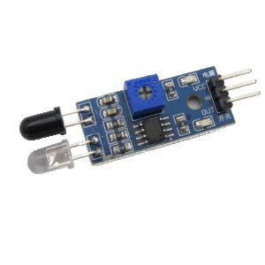
Thermistor
The thermistor is used to detect temperature changes in the environment. It provides variable resistance based on temperature.
Power Supply Module:
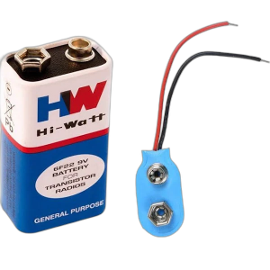
9V Battery
The 9V battery supplies power to the entire circuit, ensuring all components operate effectively.
Battery Connector
The battery connector securely connects the 9V battery to the circuit, providing a stable electrical connection.
Control Module:
Relay Module
The relay module acts as a switch that controls the fan based on the signal from the thermistor.
Signal LED
The signal LED provides visual feedback indicating the status of the control signal in the circuit.
Output Module:
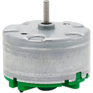
Fan
The fan operates based on the control signal to provide cooling when the temperature exceeds a certain threshold.
Buzzer
The buzzer sounds an alert, signaling that temperature has exceeded the desired range.
Status LED
The status LED indicates the operational status of the fan, showing whether it is on or off.
Other Possible Projects Using this Project Kit:
1. Automatic Room Lighting System
Using this project kit, you can create an automatic room lighting system. The thermistor, which senses temperature in the original project, can be replaced with a light-dependent resistor (LDR) to sense the ambient light level. When the light level drops below a specific threshold, the system will automatically turn on the lights using the relay module. This project is beneficial for conserving energy, as it ensures lights are only on when needed, improving the overall energy efficiency of a household or workspace.
2. Home Security Alarm System
Transform the kit into a home security alarm system by incorporating a motion sensor (PIR sensor) in place of the thermistor. The motion sensor will detect any movement within its range and trigger the buzzer module to alert homeowners of potential intruders. Additional LEDs can be used to indicate different zones of the house where motion is detected. This security system is easy to implement and provides a low-cost solution for enhancing home safety.
3. Soil Moisture-Based Irrigation System
With slight modifications, you can use this kit to develop a soil moisture-based irrigation system. Replace the thermistor with a soil moisture sensor. The sensor will monitor the moisture level in the soil and, when it drops below a pre-set threshold, will activate a water pump motor via the relay module to irrigate the plants. This system helps in automating the irrigation process, ensuring plants get the right amount of water, and promoting efficient water usage.
4. Smart Fire Detection and Alarm System
Using the components in this kit, you can create a smart fire detection and alarm system. Replace the thermistor with a smoke sensor to detect the presence of smoke in the environment. When smoke is detected, the system will activate the buzzer and LED modules to alert inhabitants of a potential fire. This project enhances safety by providing early warnings of fire hazards, potentially saving lives and property. An additional feature could be connecting a fan to extract smoke, aiding in reducing smoke inhalation risks.
| Shipping Cost |
|
No reviews found!


No comments found for this product. Be the first to comment!