


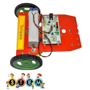


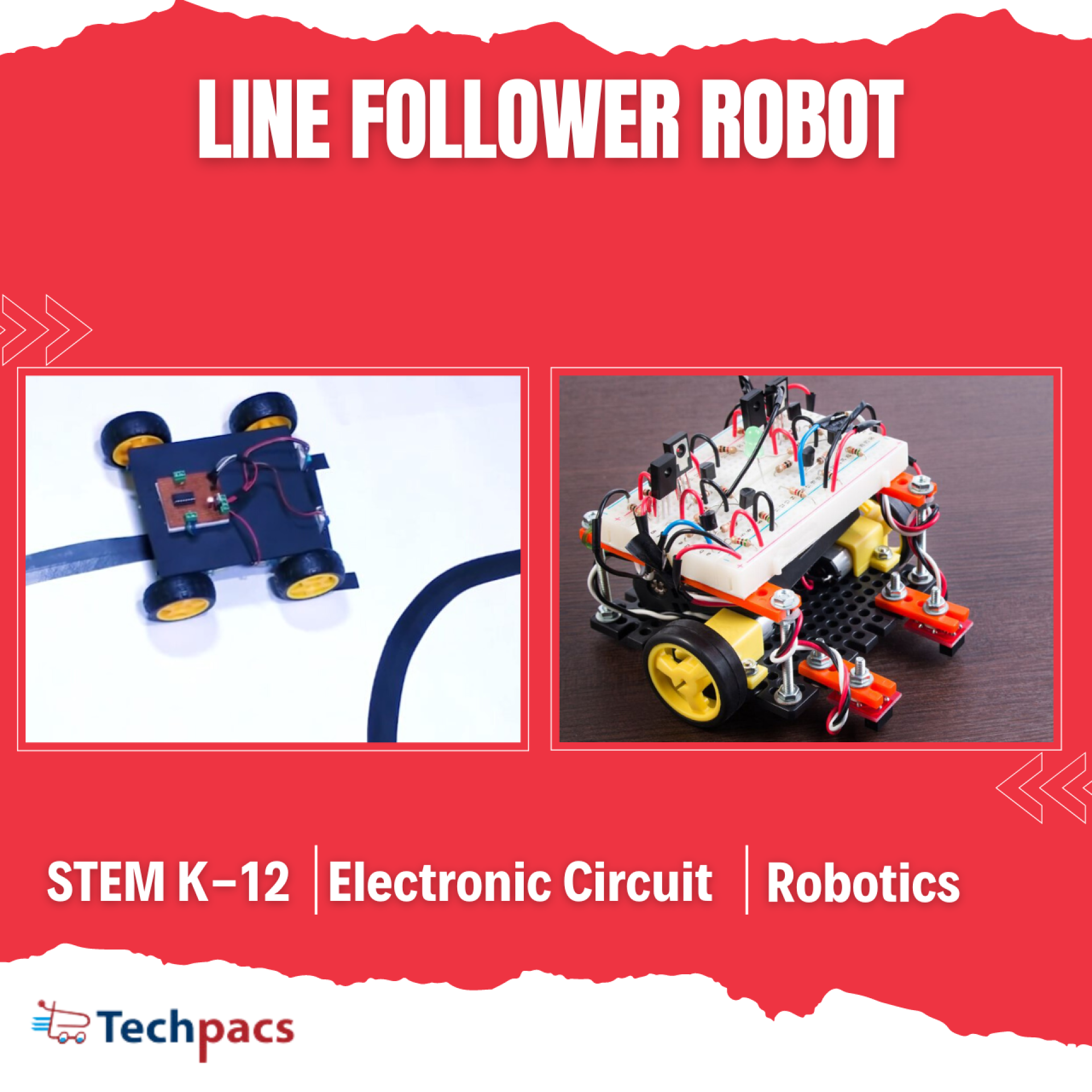
Line Follower Robot for Educational Path Following Projects
A Line Follower Robot is an autonomous robotic vehicle that follows a predetermined path, typically a line on the ground. This project is aimed at educational purposes, helping students and enthusiasts learn about robotics, electronics, and programming. The robot uses sensors to detect the line and adjusts its movement using motors to follow the path. It’s a great tool for understanding the fundamentals of automation, control systems, and sensor integration. With a simple yet effective design, this project provides a hands-on learning experience in building and operating a functional robot.
Objectives
To build an autonomous robot that follows a line traced on the floor.
To understand and implement sensor-based control in robotics.
To develop basic programming skills for controlling robotic movements.
To provide a practical learning experience in electronics and robotics.
To encourage problem-solving and critical thinking among students.
Key Features
Autonomous operation: The robot follows the line without any human intervention.
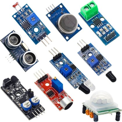
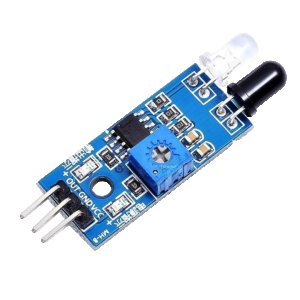
Sensor integration: Uses infrared sensors to detect and follow the line.
Motor control: Equipped with motors to navigate and drive along the path.
Rechargeable battery: Includes a charging socket and battery for extended use.
Educational value: Provides hands-on experience in robotics and electronics.
Application Areas
The Line Follower Robot has various applications, especially in educational and experimental settings. It serves as a practical project for students in schools and universities to learn about the core principles of robotics and automation. Additionally, this robot can be used in tech workshops and robotics clubs to promote STEM education. In industrial environments, line follower robots can be adapted for material handling or automated guided vehicles (AGVs) to follow predefined paths for transporting goods within a facility. Overall, its simple design and functionality make it an excellent tool for learning, experimentation, and practical applications in the field of robotics.
Detailed Working of Line Follower Robot for Educational Path Following Projects :
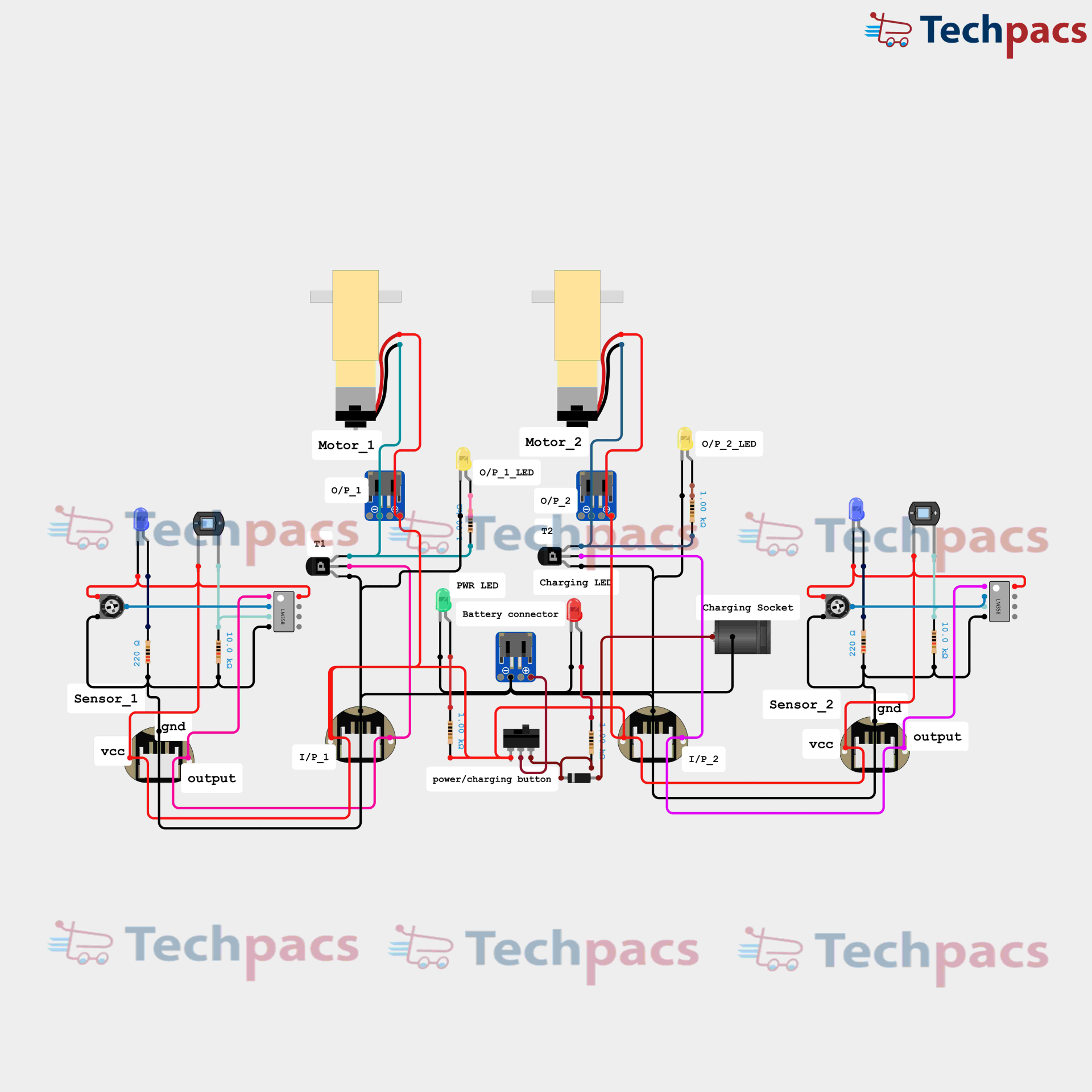
In the realm of educational path following projects, the line follower robot stands out as a classic example of how simple electronics and programming principles can come together to create a functional and engaging device. The line follower robot is designed to traverse a path defined by a black line on a white surface. This operation is made possible by a synergy of sensors, motors, and a basic control circuit.
At the heart of the line follower robot are the two main sensors, Sensor_1 and Sensor_2, which are typically infrared (IR) sensors. These sensors detect the presence of the line by differentiating between the black and white surfaces. Each sensor is connected to its respective ground (GND) and power supply (VCC) pins, ensuring they are active and ready to sense the environment. The output of each sensor is fed into the control logic of the circuit.
When both sensors detect a white surface, indicating that the robot is centered on the line, their outputs remain in a low state. This state keeps both Motor_1 and Motor_2, connected via transistors T1 and T2, running at the same speed, thereby moving the robot forward in a straight line. The transistors act as switches that control the power supplied to the motors, factoring in the sensor input to ensure proper directional control.
The complexity and beauty of the line follower robot's operation come into play when one of the sensors detects the black line while the other one continues to detect the white surface. For instance, if Sensor_1 detects the black line (output changes to high) while Sensor_2 remains on the white surface (output remains low), the circuit triggers the stopping or slowing down of Motor_1 while Motor_2 continues to run. This action causes the robot to turn or pivot towards the path until both sensors once again detect the white surface and the robot continues straight. A similar process occurs if Sensor_2 detects the line while Sensor_1 stays on the white surface, causing Motor_2 to stop or slow down and making the robot adjust its course accordingly.
In addition to the main components, the circuit also includes various LEDs serving as status indicators. For instance, the PWR LED indicates the power status of the circuit. The O/P_1_LED and O/P_2_LED are directly connected to the outputs of Sensor_1 and Sensor_2, respectively, providing visual feedback of the sensors' detection status. This setup allows users to understand and debug the robot's behavior intuitively.
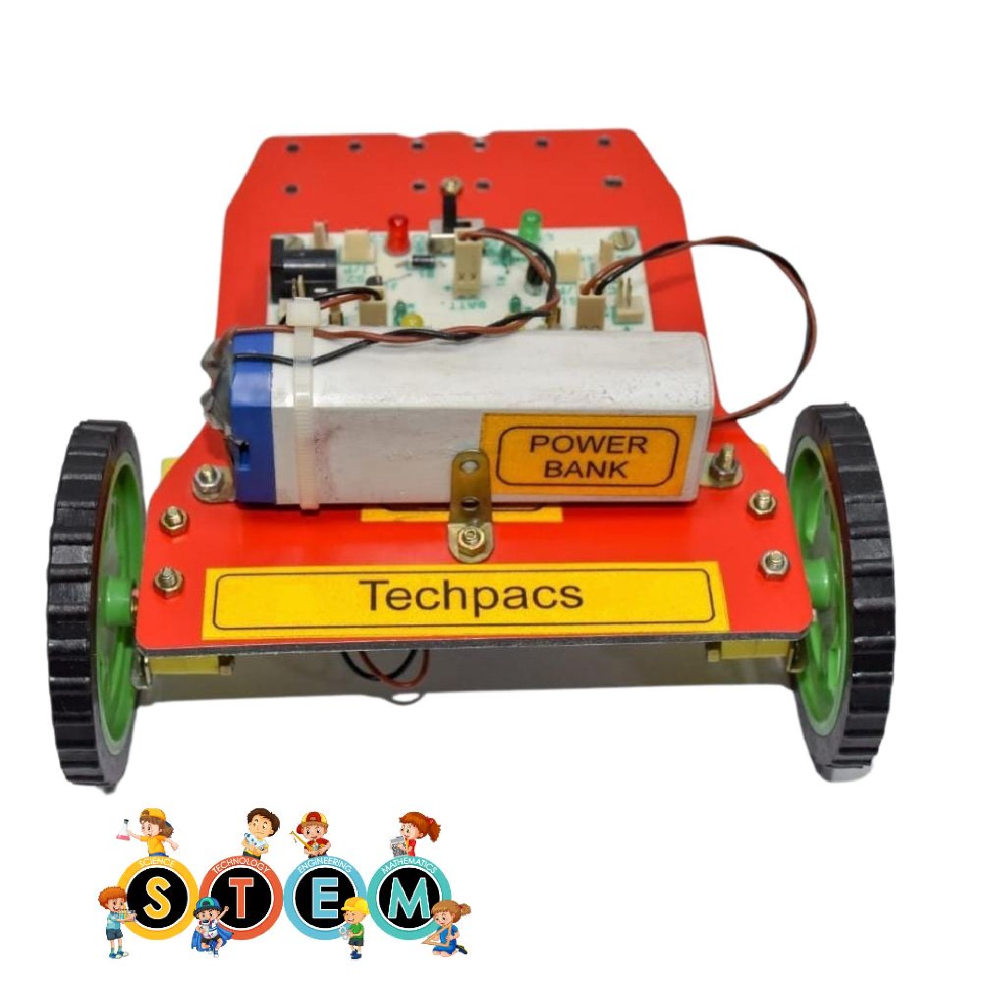
The power source for this setup is a rechargeable battery connected through a battery connector. The circuit also includes a charging socket and a charging LED to indicate when the battery is being charged, ensuring the robot can be easily recharged and reused for multiple trials and educational demonstrations. A power/charging button toggles between operational and charging states, simplifying the user interface.
The control logic, facilitated by the combination of sensors, transistors, and motor drivers, operates in a feedback loop. The sensors continuously monitor the line's position, and the control circuit makes real-time corrections to the motors' speed and direction. This dynamic interaction enables the robot to follow the line with precision, adjusting its path as needed based on the input from the sensors.
In conclusion, the line follower robot for educational path following projects exemplifies the integration of fundamental electronic components to create a practical and intuitive device. By understanding the roles of each component and their interconnections, students and hobbyists can gain valuable insights into robotics and control systems. This project not only fosters learning but also inspires creativity and innovation in the field of robotics.

Modules used to make Line Follower Robot for Educational Path Following Projects :
1. Sensor Module
The sensor module comprises primarily of two infrared sensors, Sensor_1 and Sensor_2, positioned on the left and right sides of the robot, respectively. These sensors detect the line by differentiating between the black path and white background. The sensors work by emitting infrared light and detecting the reflected light. When the sensor is above a black line, less light is reflected, indicating the robot should follow the line. The output of each sensor is connected to the respective inputs I/P_1 (for Sensor_1) and I/P_2 (for Sensor_2), which are further processed by the control and motor driver modules. This allows for real-time feedback for path correction.
2. Control Module
The control module receives the input signals from the sensor module. In this specific setup, transistors T1 and T2 act as switches that direct the input signals to control the motors. When Sensor_1 detects the black line, it sends a signal to switch T1, which in turn activates Motor_1. Similarly, Sensor_2’s output is sent to T2 to control Motor_2. The control module ensures that the robot can adjust its direction based on the sensor input, by manipulating the motor commands to keep the robot on the predefined path.
3. Motor Driver Module
The motor driver module interfaces directly with the control module and the motors (Motor_1 and Motor_2). Motor_1 and Motor_2 are connected to the robot's mechanical wheels and are responsible for the movement of the robot. Through the O/P_1 and O/P_2 signals received from the control module, the motor driver module appropriately drives each motor to turn the wheels at varying speeds. This control is crucial for handling curves and straight paths on the line-following course. LEDs connected to O/P_1 and O/P_2 provide visual indicators of motor activity.
4. Power Supply Module
The power supply module is paramount to the robot's functionality. This module includes a battery connector, charging socket, and power/charging button. The battery connector feeds power to the entire circuitry, while the charging socket allows the battery to be recharged as needed. LEDs indicate the power and charging status. Proper management of the power supply ensures that the robot remains operational for extended periods, facilitating continuous line-following tasks without frequent interruptions.
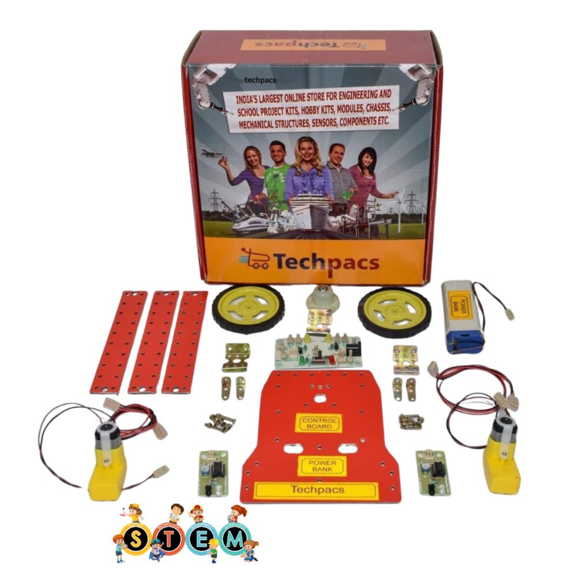
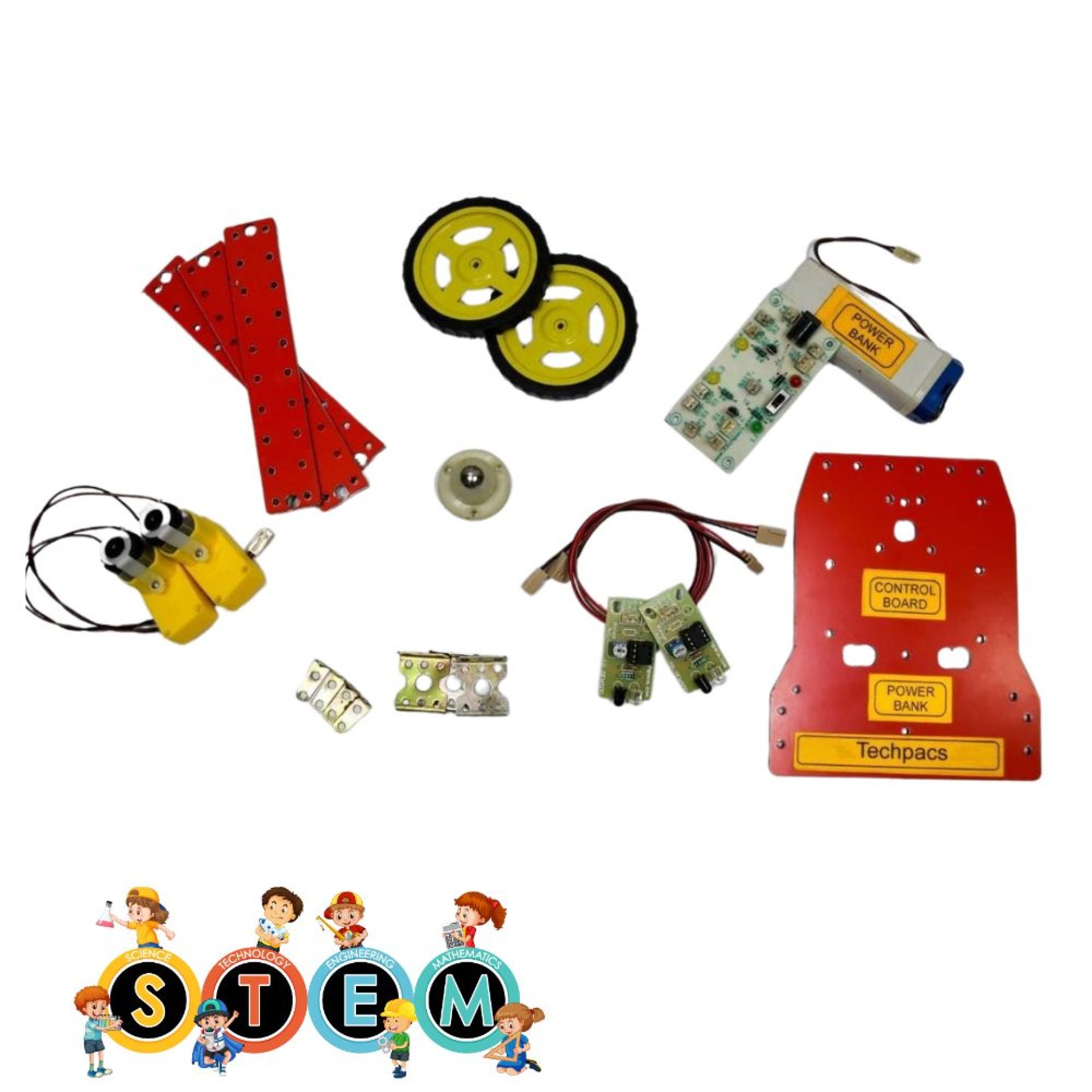
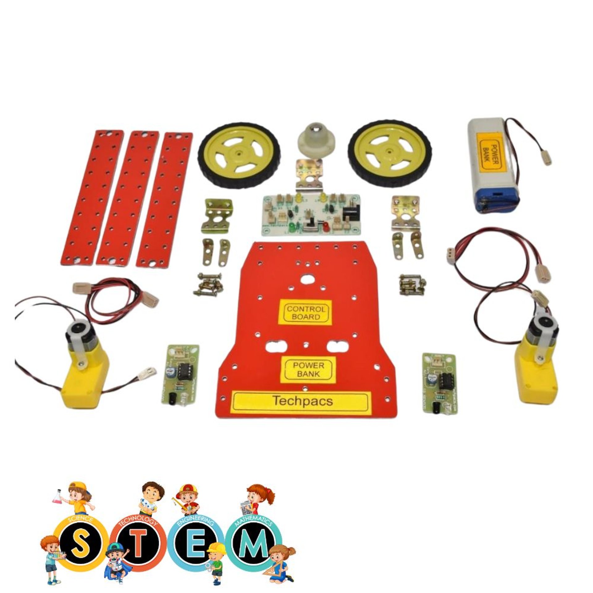
Components Used in Line Follower Robot for Educational Path Following Projects :
Motors Section
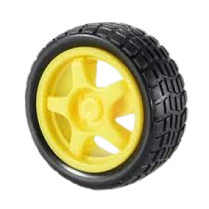
Motor_1: Drives the left wheel of the robot and helps it move forward, backward, and turn.
Motor_2: Drives the right wheel of the robot and complements Motor_1 in enabling overall movement and turns.
Sensors Section
Sensor_1: Detects the line path on the left side and sends signals to the microcontroller to adjust the motors.
Sensor_2: Detects the line path on the right side, aiding in the navigation and balance of the robot on the path.
Power and Control Section
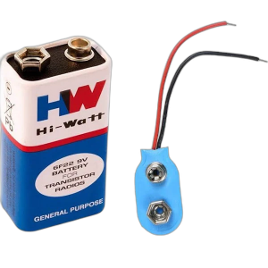
Battery Connector: Connects the battery to the circuit, providing the necessary power for the robot's operation.
Power/Charging Button: Switches the power on and off, and allows for charging the battery when needed.
Indicators Section
Power (PWR) LED: Indicates when the power is turned on, ensuring the robot is active and functional.
Charging LED: Indicates the charging status of the battery, informing the user when the charge is complete.
O/P_1 LED: Shows output signals related to the left motor's operation, helping in debugging and monitoring the robot's movements.
O/P_2 LED: Displays output signals related to the right motor's operation, assisting in the observation and troubleshooting of the robot’s actions.
Other Possible Projects Using this Project Kit:
1. Obstacle Avoidance Robot
An obstacle avoidance robot is designed to move around in its environment, detecting and avoiding obstacles in its path. Using the same project kit, you can implement additional sensors such as ultrasonic or infrared sensors to detect obstacles at a distance. The microcontroller will then process the data from the sensors, determining the distance between the robot and any obstacles. When an obstacle is detected within a certain range, the robot will alter its direction to avoid a collision. This kind of robot is beneficial in scenarios where autonomous navigation is required in dynamic environments, such as warehouses or domestic settings.
2. Edge Detection Robot
An edge detection robot uses sensors to detect the boundaries of a surface and avoid falling off. By leveraging the existing sensors in the project kit along with slight modifications, you can create a robot that moves safely across surfaces and detects edges of a table or platform. Upon detecting an edge, the robot responds by stopping or changing direction to prevent falling. This project is particularly useful for developing robots that operate on elevated platforms, aiming to ensure safety and reliable operation in constrained environments.
3. Light Following Robot
A light following robot is designed to follow light sources within its environment. Utilizing the same components in your project kit, this robot uses light sensors instead of line sensors. The microcontroller interprets data from the light sensors to determine the direction of a light source. When the light intensity on one sensor is higher than on another, the robot adjusts its direction to move towards the light. This kind of robot is perfect for experiments involving automatic lighting systems or for applications where tracking light sources is essential, such as in solar panel alignment.
4. Maze Solving Robot
The maze-solving robot can navigate through a maze and find the exit without human intervention. Using the line sensors provided in the project kit, along with effective programming algorithms such as the left-hand or right-hand rule, this robot can continuously explore paths and identify dead ends. Upon encountering a dead end, the robot backtracks and seeks alternative routes. This project demands logical programming and real-time processing, pushing the boundaries of the basic line-following robot and offering enhanced problem-solving capabilities—suitable for competitive robotics or educational exhibitions.
5. Wall Following Robot
A wall-following robot is designed to navigate parallel to walls and maintain a consistent distance from them. Using the same project kit with the integration of additional distance sensors, particularly ultrasonic sensors, this robot can measure the distance from walls in real-time. The microcontroller processes the data and makes adjustments to the robot's path to stay parallel to the wall. This project is advantageous for applications in navigation systems for indoor mapping and inspection routines in constrained environments where wall adherence and systematic exploration are required.
| Shipping Cost |
|
No reviews found!


No comments found for this product. Be the first to comment!