


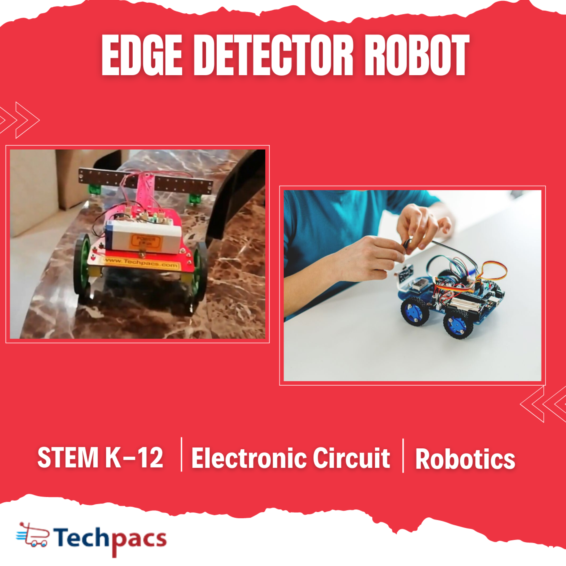
Edge Detector Robot for Accurate Navigation Systems
The Edge Detector Robot is designed for superior navigation performance through precise detection and reaction to edges and boundaries in its environment. This project integrates multiple sensors and actuators to create a system capable of operating in various terrains and environments. With a focus on real-time processing and accurate movement, the robot aims to navigate complex paths without human intervention. Implemented with a blend of hardware and software components, this project demonstrates the application of robotics in new and innovative ways for real-world challenges.
Objectives
1. To develop an autonomous robot capable of detecting and reacting to edges in its environment.
2. To implement a navigation system that ensures accurate and efficient movement along predefined paths.
3. To integrate sensor data processing for real-time decision-making in avoidance and path correction.
4. To create a versatile platform that can be adapted for various applications, including industrial and domestic usage.
5. To ensure energy-efficient operation through optimized control algorithms.
Key Features
1. High-precision edge detection sensors that allow real-time identification of boundaries.
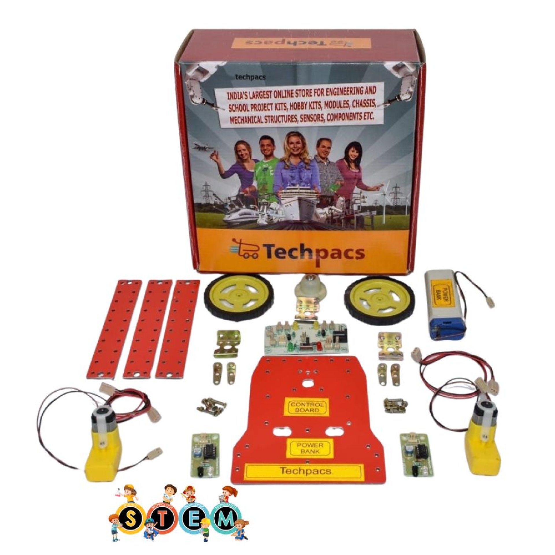
2. Dual-motor system for controlled and accurate movements in any direction.
3. Energy-efficient design with a rechargeable battery system and status indicators for power management.
4. Seamless integration of sensors, microcontrollers, and actuators for robust performance.
5. Versatile application potential in various terrains and environments, adaptable to specific needs and conditions.
Application Areas
The Edge Detector Robot serves a broad range of applications across different fields. In industrial settings, it can be used for automated guided vehicles (AGVs) to transport materials safely, avoiding hazardous edges and drop-offs. In residential areas, it can provide precise navigation for cleaning robots, ensuring efficient coverage without falling down stairs or off ledges. Additionally, this technology is highly beneficial in agricultural automation for crop monitoring and harvesting, where precise navigation is crucial. Beyond these, the robot's adaptable nature makes it suitable for research purposes in robotics and AI-driven navigation solutions, contributing to advancements in autonomous systems.
Detailed Working of Edge Detector Robot for Accurate Navigation Systems :
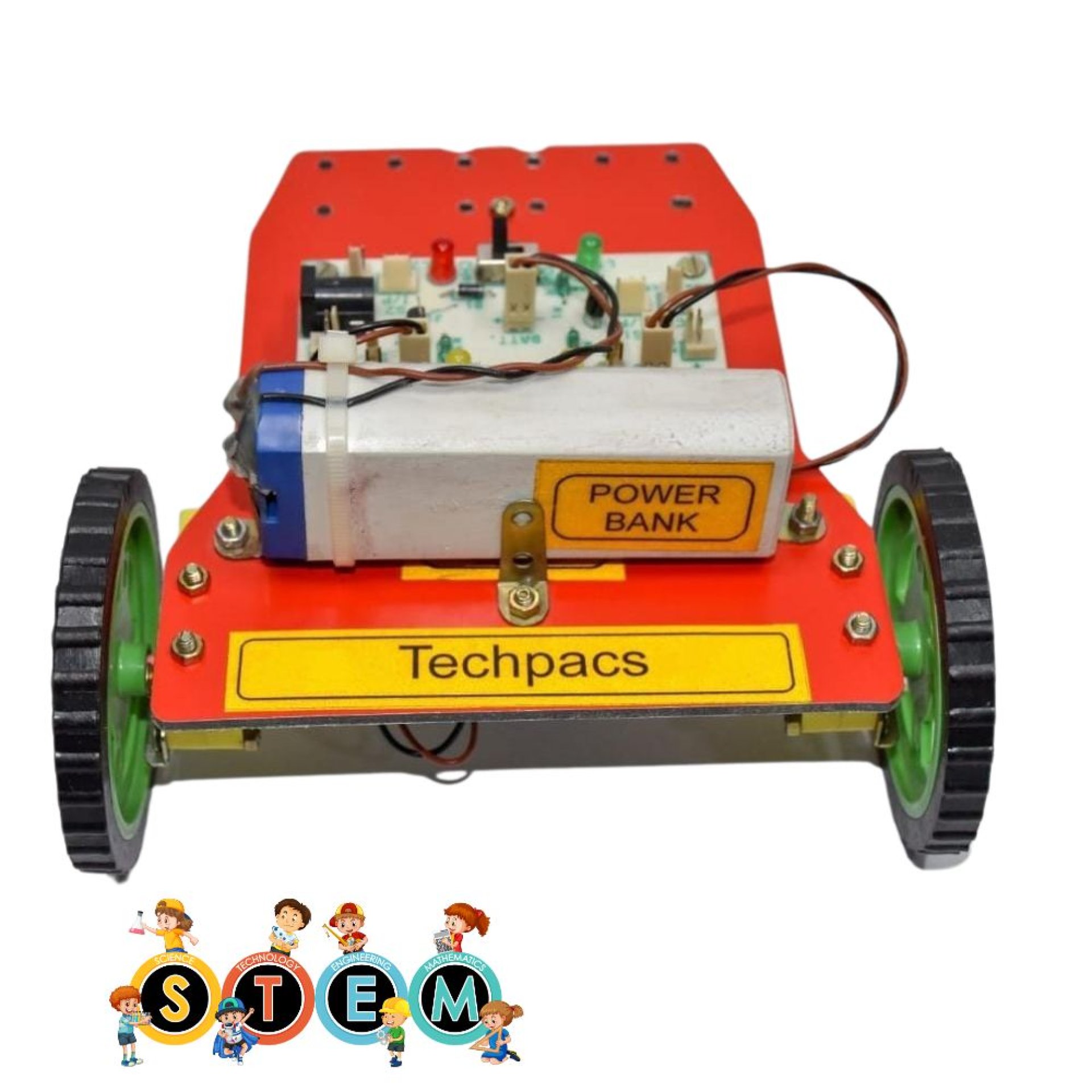
The Edge Detector Robot for Accurate Navigation Systems is designed to navigate an environment by detecting edges and avoiding falls or collisions. The core components of this circuit include sensors, motors, LEDs, and a central control unit that coordinates their functions. Let's delve into the detailed working of this intricate system.
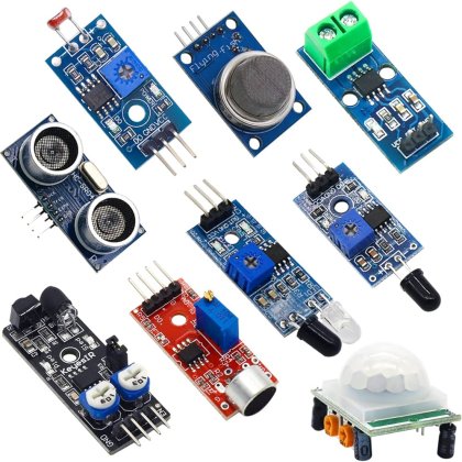
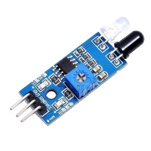
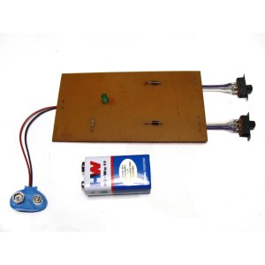
At the heart of the system are two infrared (IR) sensors labeled as Sensor_1 and Sensor_2. These sensors serve as the eyes of the robot. Positioned on the left and right sides of the robot, they continuously monitor the surface ahead for any edges or sharp turns. Each sensor outputs a signal based on the presence of an edge detected by emitting and receiving IR light. When an edge is detected, the IR light is not reflected back, leading to a change in the sensor's output signal.
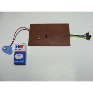
The output signals from the sensors are fed into the central processing unit, which in this case comprises two transistors labeled T1 and T2. These transistors act as switch controllers for the motors. When Sensor_1 detects an edge, it sends a signal to transistor T1, which in turn controls Motor_1. Similarly, Sensor_2 controls Motor_2 through transistor T2. This setup ensures that the motors respond instantaneously to sensor inputs, enabling quick adjustments to the robot's path.
The motors, labeled Motor_1 and Motor_2, are connected to the wheels of the robot. They are responsible for driving the robot forward or making turns. When an edge is detected by either sensor, the corresponding motor may slow down, stop, or reverse to steer the robot away from the edge. This dynamic response is crucial for maintaining the robot’s stability and preventing it from falling off edges.
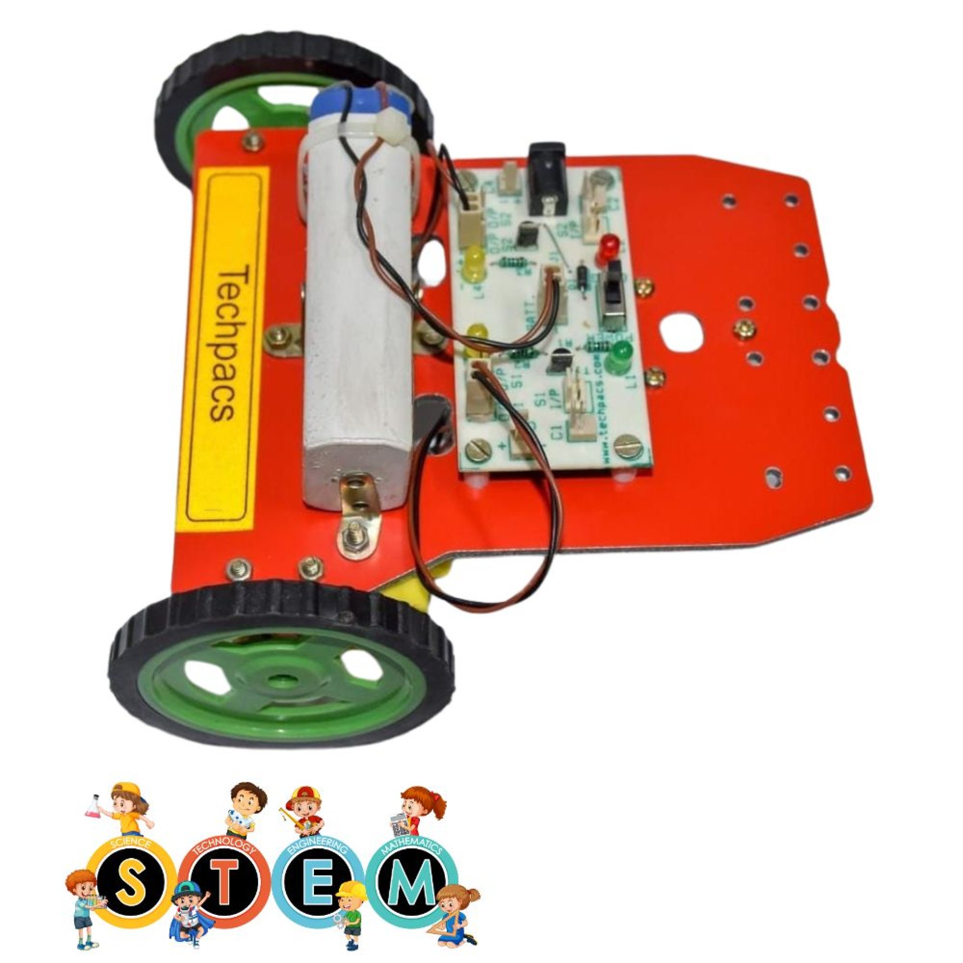
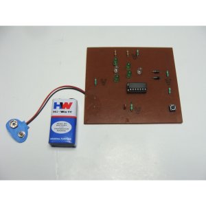
Additionally, the circuit includes several LEDs that provide visual indicators of the robot's status. The PWR LED indicates that the system is powered on, while the charging LED shows the charging status of the robot's battery. Each motor has an associated O/P (output) LED that lights up when the respective motor is active. These LEDs are helpful for debugging and monitoring the robot during operation.
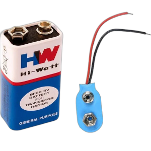
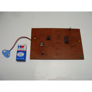
The circuit is also equipped with a battery and charging components. The battery connector and charging socket ensure that the robot can be easily recharged, maintaining consistent power supply during prolonged operations. An on/off button allows the user to power the system on and off conveniently.
In summary, the Edge Detector Robot utilizes IR sensors to detect edges and control the motors to navigate its environment safely. The responsiveness of the system is a result of the seamless integration of sensors, transistors, motors, and LEDs. This coordinated effort ensures that the robot can detect edges accurately and adjust its path promptly to avoid falling or colliding with obstacles. The power management components further enhance the efficacy of the system by providing reliable and uninterrupted power, making it a robust solution for edge detection and accurate navigation.
Modules used to make Edge Detector Robot for Accurate Navigation Systems :
1. Sensor Module
The sensor module consists of IR sensors (Sensor_1 and Sensor_2) that are responsible for detecting the edges or lines. Each sensor array contains an emitter and a receiver which work by emitting infrared light and detecting the reflected signals. If the signal is reflected back to the sensor, it indicates the presence of a surface or line. The sensors are connected to the power (vcc) and ground (gnd) lines, with their outputs feeding into the processing module. The data signals from the outputs of the IR sensors are essential as they provide the real-time input required to determine the robot's proximity to edges, allowing the robot to navigate accurately by detecting boundaries and edges present in the environment.
2. Processing Module
The processing module is essentially where the logic of the robot is implemented. This module makes use of transistors (T1 and T2) that act as switches to control the motor drivers. Each transistor is triggered based on the input received from the sensor module. If an edge is detected by a sensor, it turns the respective transistor on or off, which feeds the signal into the motors to adjust their behavior. The inputs (I/P_1 and I/P_2) help determine whether the robot should continue moving forward or make a turn to avoid falling off an edge. This module is crucial for decision-making and ensures that the robot acts based on incoming sensory data.
3. Motor Driver Module
The motor driver module connects directly to the motors (Motor_1 and Motor_2) and is responsible for controlling the direction and speed of the robot. This module receives the processed signals from the transistors, which determine if the motors should be powered on or off. Based on the signals, the motor drivers adjust the rotation, ensuring the robot can move forward, stop, or take a turn as needed. This is essential for implementing the movement commands determined by the processing module. The LEDs (O/P_1_LED and O/P_2_LED) provide visual feedback about the state of each motor driver, indicating whether power is being supplied to the motors.
4. Power Management Module
The power management module provides and regulates power to the entire circuit. It includes a battery connector and a charging socket, allowing for convenient powering and recharging of the system. The power/charging button allows toggling between powering on the circuit and charging the batteries. Additionally, LEDs (PWR LED and Charging LED) are used to display the current power state, indicating when the system is active or when it’s charging. Stable power supply is critical for reliable operation of the robot, ensuring that all components receive the necessary voltage and current to function correctly.
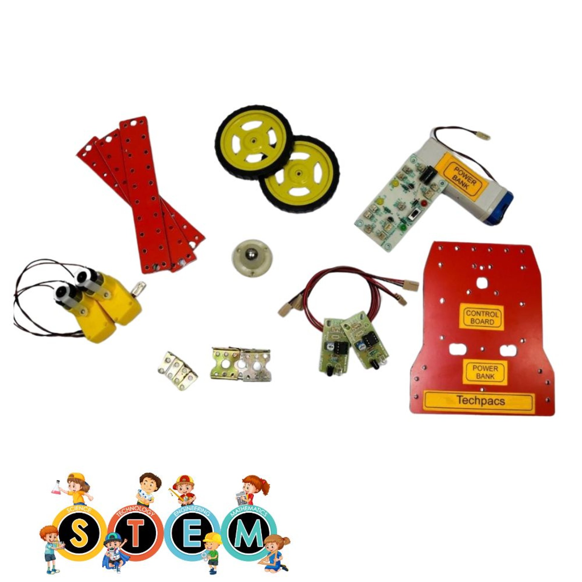
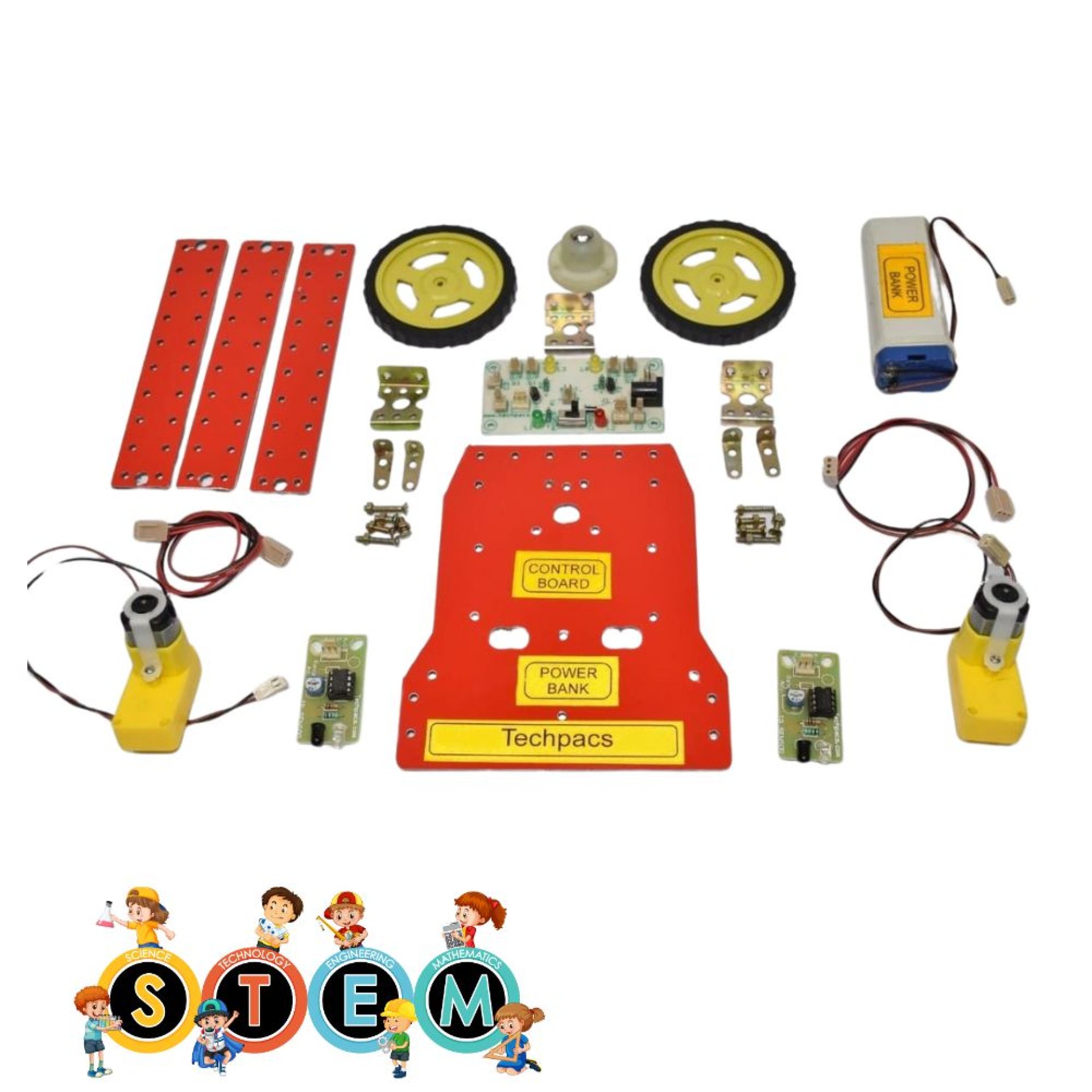
Components Used in Edge Detector Robot for Accurate Navigation Systems :
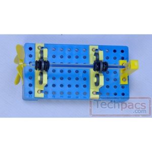
Motor Module
Motor_1: Provides rotational motion necessary for the robot to move.
Motor_2: Works in tandem with Motor_1 to ensure balanced movement.
Sensor Module
Sensor_1: Detects edges to help the robot identify boundaries.
Sensor_2: Works with Sensor_1 to improve edge detection accuracy.
Indicator LEDs
O/P_1_LED: Indicate the output status of the respective motor driver output.
O/P_2_LED: Indicate the output status of the respective motor driver output.
PWR_LED: Shows power availability for the robot operation.
Charging_LED: Indicates charging status of the robot’s battery.
Power Supply Module
Battery Connector: Connects the battery to the circuit, providing necessary power.
Charging Socket: Used to connect an external charger for recharging the battery.
Power/Charging Button: Toggles between power on and charging mode.
Input/Output Module
I/P_1: Input signal for sensor signals or control instructions.
I/P_2: Additional input signal for sensor signals or control instructions.
O/P_1: Output signal to control Motor_1 based on sensor input.
O/P_2: Output signal to control Motor_2 based on sensor input.
Other Possible Projects Using this Project Kit:
1. Line Following Robot
A line following robot is a type of autonomous robot that follows a predetermined path, usually marked by a black line on a white surface or vice versa. Using the sensors provided in the kit, this project can be easily accomplished. The sensors detect the contrast between the line and the background and send signals to the microcontroller to control the motor speed and direction. By adjusting the sensors and their positions, the robot can navigate turns and curves, making it a great project to teach the basics of sensor integration and real-time data processing.
2. Obstacle Avoidance Robot
An obstacle avoidance robot navigates its environment by detecting and avoiding obstacles in its path. This can be achieved by using ultrasonic sensors to measure the distance to objects ahead and steer away from them. The project kit can provide the basic structure and components needed for this task, such as the microcontroller, motors, and sensors. By programming the microcontroller to change the robot’s direction whenever an obstacle is detected within a certain range, you can create a robot capable of moving through a cluttered environment without collisions.
3. Remote Controlled Robot
A remote-controlled robot can be designed using the existing project kit by incorporating a wireless communication module (such as Bluetooth or RF modules) for remote operation. The microcontroller serves as the central unit to receive instructions from a remote control device and translate them into actions performed by the robot. This project showcases the integration of wireless technology and provides learners with practical experience in developing remote control systems, which can be applied to various applications, from toy cars to industrial automation.
| Shipping Cost |
|
No reviews found!


No comments found for this product. Be the first to comment!